3GPP 5G New Radio (NR) Test Solution
with ADP7104, M8190A, M8195A, WR28CCU, WR28CCD, N5183B
- Generate and analyze 3GPP 5G NR, non-standalone 5G NR and 5G TF waveforms
- Pre-correct waveforms for overall channel response
- Supports many topologies for transmitter / receiver testing (IQ, IF, RF, microwave, millimeter-wave)
- Independent reference to debug and validate hardware performance
- 2 channel RF modulation bandwidths up to 8.5 GHz (4 channel 6.5 GHz)
- Frequency bands between DC and 10 GHz with base instruments
- Frequency bands between 22.5 – 40 GHz with extended millimeter-wave configurations
- Over-the-Air (OTA) measurements using waveguide horn antennas
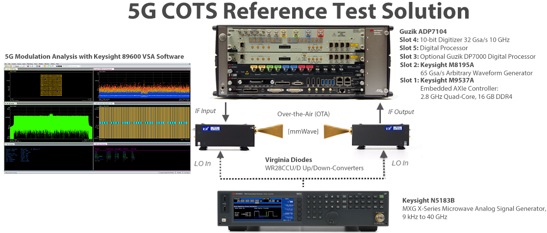
5th generation mobile networks or 5th generation wireless systems, abbreviated 5G, are the next telecommunications standards beyond the current 4G/IMT-Advanced standards, operating in the millimeter wave bands (3.5, 28 and future 39, 60 GHz).
The 5G New Radio (5G NR) Flexible Test Solution allows to generate and analyze multichannel 5G NR, Verizon 5G and pre-5G waveforms for complete component, subsystem, and system performance at baseband, IF, and millimeter-wave. This Compact Reference Solution combines COTS modular hardware and software from Guzik, Keysight Technologies and Virginia Diodes, which provides a flexible testbed for 5G waveform generation and analysis with greater accuracy than the competitive offerings. With a residual error vector magnitude (EVM) measurements down to 0.5% (-46.0 dB) for sub-6GHz and 0.75% (-42.5 dB) for mmWave. The test setup allows to de-embed external cables, attenuators or amplifiers in front of the digitizer with Guzik patented FPGA-based interleaved ADC amplitude and phase response equalizer. Digital Equalization of mmWave Analog Frequency Up and Down-converters is described here.
Software provides the flexibility to generate and analyze 5G waveforms with a wide range of different attributes.
Modular hardware provides the flexibility to support baseband, IF, and millimeter-wave test planes. Patented FPGA-based Real-Time Digital Downconversion (DDC) can be used to greatly improve measurement speeds.
Frequencies up to 10 GHz can be supported with the base test equipment configuration for testing with a wide range of IF’s and the 28 and 39 GHz Ka-Band frequencies can be generated and analyzed with the Virginia Diodes compact up-converters and down-converters.
This Reference Solution can be used as an independent reference to help debug and validate hardware performance issues as they occur.
Recommended mmWave reference configuration with M8195A 64 Gsa/s AWG:
Recommended sub-6GHz reference configuration with M8190A 12 Gsa/s AWG:
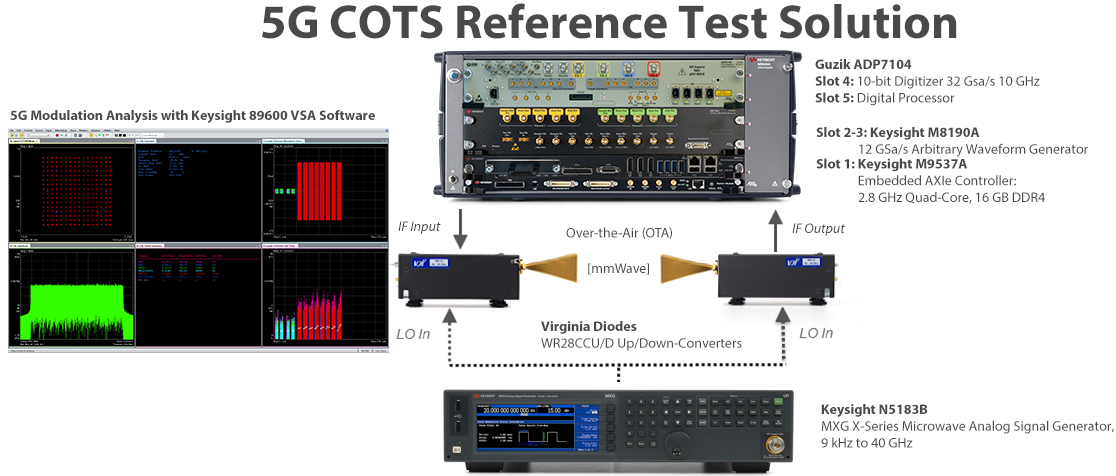
Signal creation and measurement applications and software
- Keysight N7631C Signal Studio for 5G NR waveforms.
- Keysight N7630C Signal Studio for 5G and pre-5G waveforms.
- Keysight N7608B Signal Studio for custom modulation software to create custom IQ, OFDM, and FBMC waveforms
- Keysight 89600 VSA software to demodulate 5G NR/Pre-5G waveforms (option BHN), custom IQ (BHK), and custom OFDM (BHF) waveforms
sub-6GHz Band Reference Setup with base instruments.
5G NR Downlink SS/PBCH with 8 SSBlocks (L=8) and PDSCH with 256QAM modulation performance:
FR1 100 MHz, the Max RB for 30kHz at 950 MHz center frequency – EVM 0.46% (-46.7 dB)
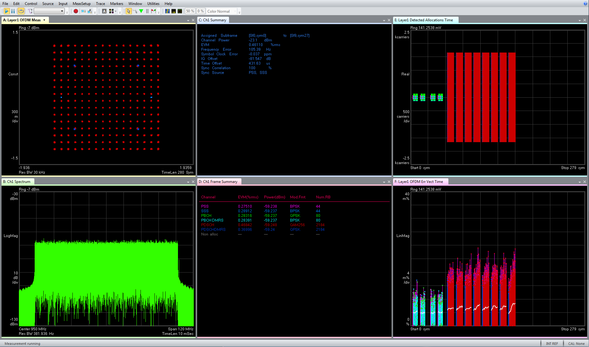
Trace A: Composite constellation diagram showing QPSK for PBCH and DMRS; BPSK for PSS/SSS and 256QAM for PDSCH. Zoom in on the QPSK symbol to see the DMRS symbol (Blue color).
Trace C: Summary trace showing composite error metrics.
Trace D: Frame Summary (Physical Channel Info trace). EVM, Power, Mod Format and Number of RB of individual channels/signals.
Trace E: Detected Allocations Time showing the detected allocations of all channels/signals within the measurement interval.
Trace E: Error Vector Time showing the 8 SSBlocks (L=8).
5G NR Uplink PUSCH with 256QAM modulation performance:
FR1 100 MHz, the Max RB for 30kHz at 950 MHz center frequency – EVM 0.32% (-49.9 dB)
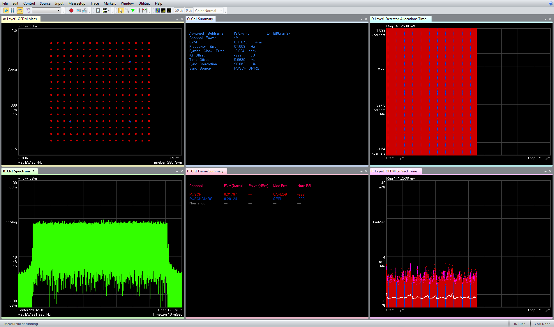
Trace A: Composite constellation diagram showing 256QAM constellation for PUSCH data and QPSK constellation for PUSCH-DMRS.
Trace C: Summary trace showing composite error metrics.
Trace D: Frame Summary (Physical Channel Info trace). EVM, Power, Mod Format and Number of RB of individual channels/signals.
Trace E: Detected Allocations Time showing the detected allocations of all channels/signals within the measurement interval.
Trace F: It shows the PUSCH data and DMRS (blue).
mmWave WR-28 Waveguide Band Reference Setup.
- VDI28.0BPFE27.5-28.35 bandpass filter with Insertion Loss < 1 dB
- VDI28.0BPFE37-40 bandpass filter with Insertion Loss < 1 dB
The measurements below in the mm-wave range are performed via waveguide interface WR-28 for simplicity.
Radiated emission over-the-air (OTA) measurements with waveguide horn antennas can lead to high attenuation. Each ADP7104 digitizer channel has adjustable front-end (-32 dBm to +22 dBm with 1 dB steps), which allows to fine tune the receiver for best EVM.
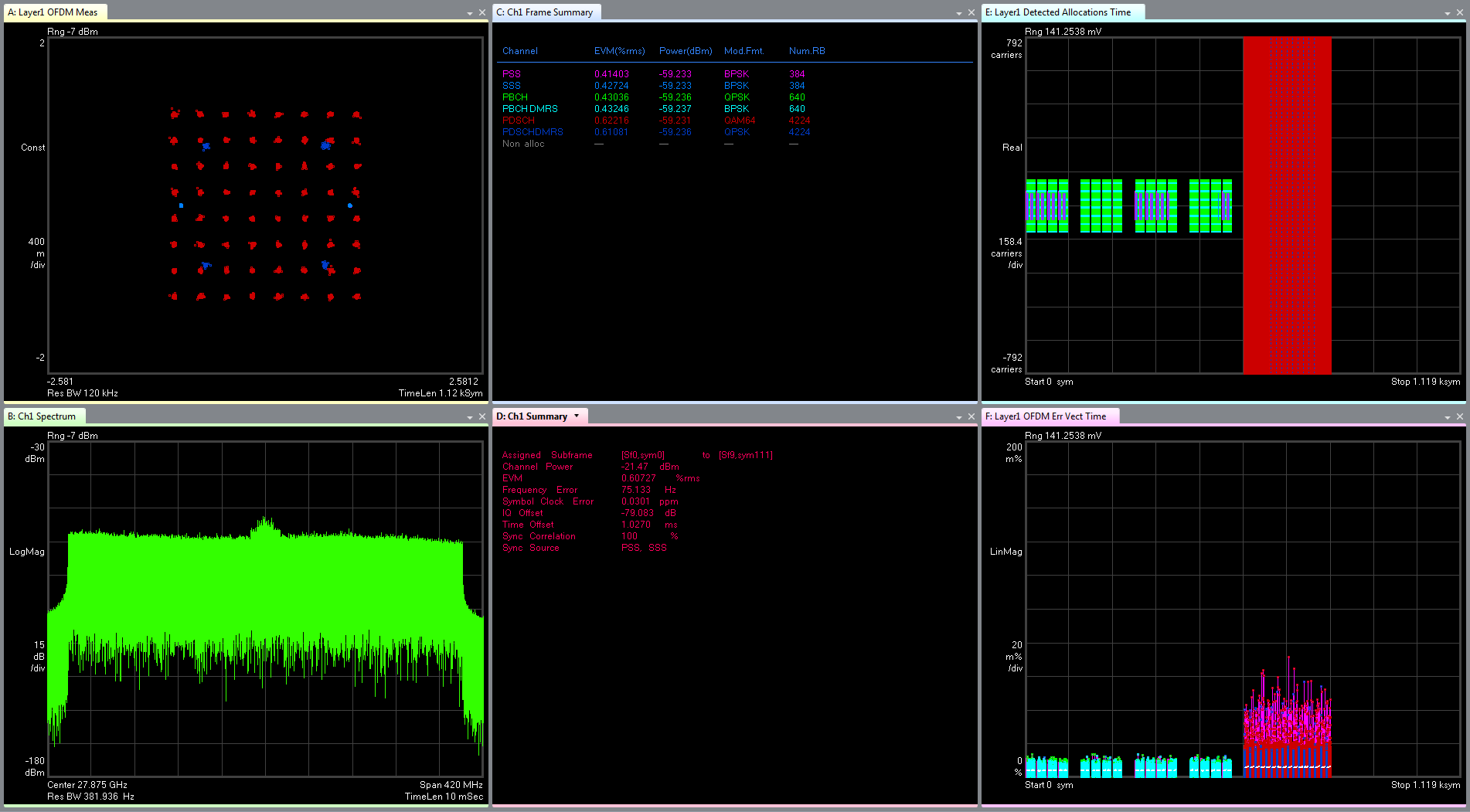
mmWave 5G NR Downlink SS/PBCH with 64 SSBlocks (L=64) and PDSCH with 64QAM modulation performance:
FR2 400 MHz, the Max RB for 120kHz at 27.875 GHz center frequency – EVM 0.61% (-44.3 dB)
FR2 400 MHz, the Max RB for 120kHz at 39 GHz center frequency – EVM 0.7% (-43.1 dB)
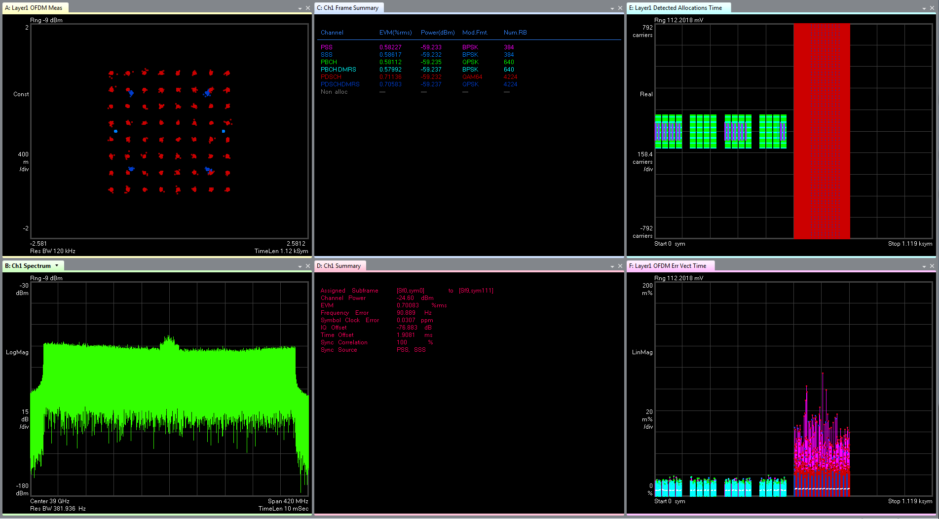
Trace A: Composite constellation diagram showing QPSK for PBCH and DMRS; BPSK for PSS/SSS and 64QAM for PDSCH. Zoom in on the QPSK symbol to see the DMRS symbol (Blue color).
Trace C: Summary trace showing composite error metrics.
Trace D: Frame Summary (Physical Channel Info trace). EVM, Power, Mod Format and Number of RB of individual channels/signals
Trace E: Detected Allocations Time showing the detected allocations of all channels/signals within the measurement interval.
Trace E: Error Vector Time showing the 64 SSBlocks (L=64).
Note: Application Sample measurement results provided are representative and performed under ideal conditions without “Pre-Corrections” at +25˚C ambient temperature. The results are not warranted specifications.
Application demonstration:
In collaboration with Florida International University PhD student Dimitrios Siafarikas, a pre-6G system was designed to demonstrate the feasibility of higher data rates. This system demonstrates a live OTA wireless link at D-band with an average data rate of 30 gigabits/sec and a peak data rate of 48 gigabits/sec.
1 Channel Configuration:
The analysis speed greatly depends of the processing capability available to the test solution, either as an integrated measurement personality or as software running internally on a computer connected to signal analyzer. As the 5G NR subframes grow in complexity and bandwidth, the signal analyzers have a tough time keeping up with delivering the analysis speed necessary for high-volume manufacturing.
The Guzik ADP7104 Series 10-bit Digitizer is employing techniques similar to most digital radio receivers for decoding digital modulations. The digitizer can directly sample RF signals at DC to 10 GHz on multiple channels simultaneously and in Real-Time Digitally Downconvert (DDC) the signals from any center frequency within the digitizer bandwidth to digital I-Q baseband. This technique provides all digital fast high accuracy repeatable measurements and display of modulation characteristics by reducing both front-end active analog signal chain components and supporting elements. More info here.
With the FPGA-based digital signal processing capabilities in the Guzik ADP7104 Series 10-bit Digitizer, the overall measurement process is accelerated to enable the sub 1 second measurement speed requirements for 5G NR analysis both during R&D and volume manufacturing.
sub-6GHz Band reference configuration with M8195A 64 Gsa/s AWG and Frame Trigger Present.
5G NR Downlink SS/PBCH with 8 SSBlocks (L=8) and PDSCH with 256QAM modulation performance:
FR1 100 MHz, the Max RB for 30kHz at 1 GHz center frequency – EVM measurement time ~110ms (1 subframe result length).
Trace C: Summary trace showing composite error metrics.
Measurement time ~280ms (1 subframe result length with additional traces):
Trace A: Composite constellation diagram showing QPSK for PBCH and DMRS; BPSK for PSS/SSS and 256QAM for PDSCH. Zoom in on the QPSK symbol to see the DMRS symbol (Blue color).
Trace C: Summary trace showing composite error metrics.
Trace D: Error Vector Spectrum.
Trace E: Detected Allocations Time showing the detected allocations of all channels/signals within the measurement interval.
Trace F: Frame Summary (Physical Channel Info trace). EVM, Power, Mod Format and Number of RB of individual channels/signals.
5G NR Downlink SS/PBCH with 64 SSBlocks (L=64) and PDSCH with 256QAM modulation performance:
FR2 400 MHz, the Max RB for 120kHz at 1 GHz center frequency – EVM measurement time ~320ms (1 subframe result length).
Trace C: Summary trace showing composite error metrics.
Measurement time ~750ms (1 subframe result length with additional traces):
Trace A: Composite constellation diagram showing QPSK for PBCH and DMRS; BPSK for PSS/SSS and 256QAM for PDSCH. Zoom in on the QPSK symbol to see the DMRS symbol (Blue color).
Trace C: Summary trace showing composite error metrics.
Trace D: Error Vector Spectrum.
Trace E: Detected Allocations Time showing the detected allocations of all channels/signals within the measurement interval.
Trace F: Frame Summary (Physical Channel Info trace). EVM, Power, Mod Format and Number of RB of individual channels/signals.
Note: Application Sample measurement results provided are representative and performed under ideal conditions without “Pre-Corrections” at +25˚C ambient temperature. The results are not warranted specifications.

