FPGA Accelerated VSA
with Guzik ADP7000 Series 10-bit Digitizers and DP7000 FPGA-based digital processors
- Keysight Vector Signal Analyzer (VSA) 89600 Software accelerated by the Real-Time Digital Down-Converter (DDC) with equalization
-
DDC center frequency tuning resolution 0.0018 Hz for 32Gsa/s, 0.0009 Hz for 16 Gsa/s mode (ADP7104); 0.0011 Hz for 20Gsa/s, 0.0006 Hz for 10 Gsa/s mode (ADP7084)
-
DDC user-span 1 Hz (ADP7104); 0.6 Hz (ADP7084) resolution, 1.28 oversampling factor with arbitrary re-sampling and decimation output
-
Direct RF sampling provides a higher level of integration and reduces both active signal chain components and supporting elements

Vector Signal Analysis
It is known that VSA capability depends on the processing capability available to the analyzer front end, either as an integrated measurement personality or as software running internally on a computer connected to the front end. As the signals that people must analyze are growing in complexity and bandwidth, the latest generations of signal analyzers have moved to a digital architecture and often include many vector signal analysis and modulation analysis capabilities.
VSA can be viewed as a software-based measurement receiver. The Guzik ADP7104 Series 10-bit Digitizer is employing techniques similar to most digital radio receivers for decoding digital modulations. The digitizer can directly sample RF signals at DC to 10 GHz on multiple channels simultaneously and in Real-Time Digitally Downconvert (DDC) the signals to digital I-Q baseband. This technique provides all digital fast high accuracy repeatable measurements and display of modulation characteristics by reducing both active signal chain components and supporting elements.
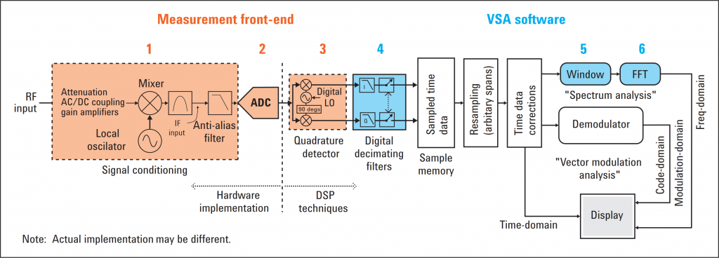
Figure 1 shows a generalized diagram of the technique that Keysight Technologies, Inc. uses with the VSA 89600 Software. The VSA measurement process includes these fundamental stages:
Measurement front-end
1. Signal conditioning with frequency translation. Depending on the front-end hardware used, different signal conditioning steps may be needed and/or available
2. Analog-to-digital conversion
3. Quadrature detection
VSA software
4. Digital filtering and resampling
5. Data windowing
6. FFT analysis (for vector modulation, blocks 5 and 6 are replaced with the demodulator block)

Figure 1. Simplified block diagram showing RF hardware front end and vector signal analysis software.
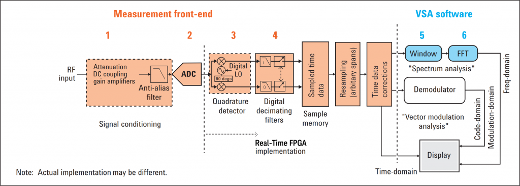
Figure 2 shows a generalized diagram of the technique that Guzik Technical Enterprises uses with the Keysight VSA 89600 Software to provide accelerated VSA measurements:
Measurement front-end
1. Signal conditioning
2. Direct RF wideband Analog-to-digital conversion
3. Quadrature detection
4. Digital filtering and resampling
VSA software
5. Data windowing
6. FFT analysis (for vector modulation, blocks 5 and 6 are replaced with the demodulator block)

Figure 2. Simplified block diagram showing direct RF hardware front-end with wideband ADC and FPGA-based DSP to accelerate vector signal analysis.
Quadrature Detector and time domain data corrections
At the heart of the DSP block is the digital downconversion, equalization filtering, resampling and decimation process.

Figure 3. Simplified block diagram of a VSA measurement system with Guzik ADP7104 Digitizer as the RF measurement front-end.
In vector analysis, the time data’s accuracy is very important. Not only is it the basis for all of the demodulation measurements, but it is also used directly for measurements such as instantaneous power as a function of time. Correcting the time data is an essential step in creating a nearly ideal bandlimiting signal path. While the digital filters and resampling algorithms provide for arbitrary bandwidths (sample rates and spans), the time-domain corrections determine the final passband characteristic of the signal path. Time-domain corrections would be unnecessary if the analog and digital signal paths could be made ideal. Time-domain corrections function as an equalization filter to compensate for passband imperfections. These imperfections come from many sources. The input amplifiers, attenuators in the RF section, the analog anti-aliasing filter and the time interleaved ADC-s all contribute to passband ripple and phase nonlinearities.
The patented digital down converter with an equalizer translates an ADC output signal to a low frequency spectral region, followed by decimation. All operations of correction of the processed signal are carried out with a reduced sampling rate compared with sampling rates of the prior art. Equalization is performed only in a frequency pass band of the down converter. The achieved reduction of the required computation resources is sufficient to enable the down converter with equalization to operate in a real time mode at up to 32 Giga samples per second (Gsa/s).
The data from the ADC is transferred directly to the DDC with digital equalizer, then to the memory and from memory to the analysis software. The down conversion is implemented by two multipliers with Sin/Cos LO signals. The LO signals area created per channel settable with a 44-bit Numerically Controlled Oscillator (NCO) design inside the FPGA-s and allows to set the DDC center frequency per channel with 0.0018 Hz resolution for 32 Gsa/s and 0.0009 Hz for 16 GSa/s mode.
Down converted signals connected through LPF/decimator to I/Q memory and are then transferred to PC.
Real-Time DDC per channel settable user-span has a 1 Hz setting resolution and has an oversampling factor of 1.28x. For a signal with 1 GHz user-span the DDC output data-rate is 1.28 GSa/s. Each sample pair of I & Q is coded on 16/32 bits (8/16-bit I and 8/16-bit Q). For every user span bandwidth reduction by four, the signal to-noise ratio (SNR) is improved by 6 dB or 1 bit of vertical resolution.
The Real-Time IF magnitude trigger allows setting a level the signal needs to achieve at a specified center frequency per channel and allows the data for the signal of interest to pass to the I/Q memory this allows to Start and Stop Variable Length Segments on the IF Magnitude.
Note: ADC_ADDCRT1 option license is required to enable the Real-Time DDC, ADC_BB option license is required to control the de-embedding equalizer and ADC_VSM1 option license is required to enable Variable Length Segment Mode. Maximum supported Real-Time down converter user span for the modulated signal is 2.5 GHz for 16G/32 Gsa/s mode.
In many applications input signal can be easily down converted with the use of up-front analog down converter to the Intermediate Frequency (IF) within the analog signal bandwidth of the ADP7104. The same digital equalization technology can then be extended to external mmWave down-converters which are working together with the wideband digitizer to create a calibrated receiver. Read more here.
With the FPGA-based digital signal processing capabilities in the Guzik ADP7104 10-bit 16/32 Gsa/s Digitizer, the overall VSA process is accelerated to enable modern performance requirements and test margins for complex waveform analysis.
Moving the digital signal processing to programmable FPGA-s, shown in Figure 2, can dramatically speedup the VSA measurements allowing to test more products in less time while ensuring measurement continuity from design to manufacturing as demonstrated below.
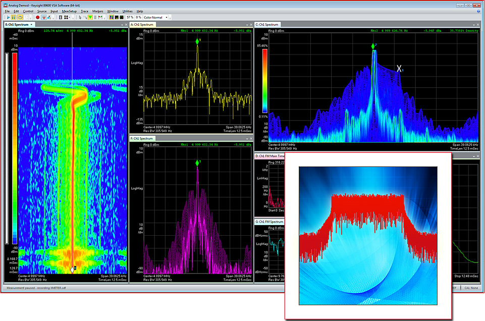
Spectrum trace of a 8.5 GHz Continuous Wave (CW) signal tuned and zoomed by a 1 GHz wide DDC and displayed with 10 kHz Resolution BW. Spectrum rate indicator displays the speed at which the measurements are being made in GHz per second:
Spectrum trace of a 8.5 GHz Continuous Wave (CW) signal tuned and zoomed by a 10 MHz wide DDC, displayed with 1 kHz Resolution BW and running number of RMS averages:
To find out more refer to Vector Signal Analysis Basics Keysight Application Note here.
Vector Signal Analysis Background
Analog, swept-tuned spectrum analyzers use superheterodyne technology to cover wide frequency ranges; from audio, through microwave, to millimeter frequencies. Fast Fourier transform (FFT) analyzers use digital signal processing (DSP) to provide high-resolution spectrum and network analysis. Today’s wide-bandwidth, vector-modulated (also called complex or digitally modulated), time-varying signals benefit greatly from the capabilities of FFT analysis and other DSP techniques. VSA provides fast, high-resolution spectrum measurements, demodulation, and advanced time-domain analysis. VSA is especially useful for characterizing complex signals such as burst, transient, or modulated signals used in communications, video, broadcast, radar, and software-defined radio applications.
VSA implements a very different measurement approach than traditional swept analysis; the analog IF section is replaced by a digital IF section incorporating digital signal processing and FFT. Traditional swept-tuned spectrum analysis is an analog system; VSA is fundamentally a digital system that uses digital data and mathematical algorithms to perform data analysis.
A significant characteristic of VSA is that it can measure and manipulate complex data, i.e. magnitude and phase information. In fact, it is called vector signal analysis, because it takes complex input data, performs complex data analysis, and outputs complex data results that include both magnitude and phase information. Vector modulation analysis performs the basic functionality of a measurement receiver.
With the proper front end, VSA covers RF and microwave ranges, plus it provides additional modulation-domain analysis capability. These advancements are made possible through digital technologies such as analog-to-digital conversion and DSP that include digital intermediate frequency (IF) techniques and fast Fourier transform (FFT) analysis.

