Wideband Channel Sounding
reference solution for mmWave WLAN and 5G
- Signal generation and capturing
- mmWave frequency bands (V-band 40-75 GHz) with Ultra-broad bandwidth (10 GHz)
- SISO and MIMO multi-channel system
- Calibration and synchronization
- Calibrated receiver with built-in IF amplifier (-32 dBm to +22 dBm FS)
- Receiver with real-time Signal Waveform Averaging
(Much higher dynamic range compared to VNA-based solutions) - Receiver with real-time Digital Down-Conversion (DDC)
- Receiver with real-time FPGA-based de-embedding equalizer
- Channel parameter estimation processing
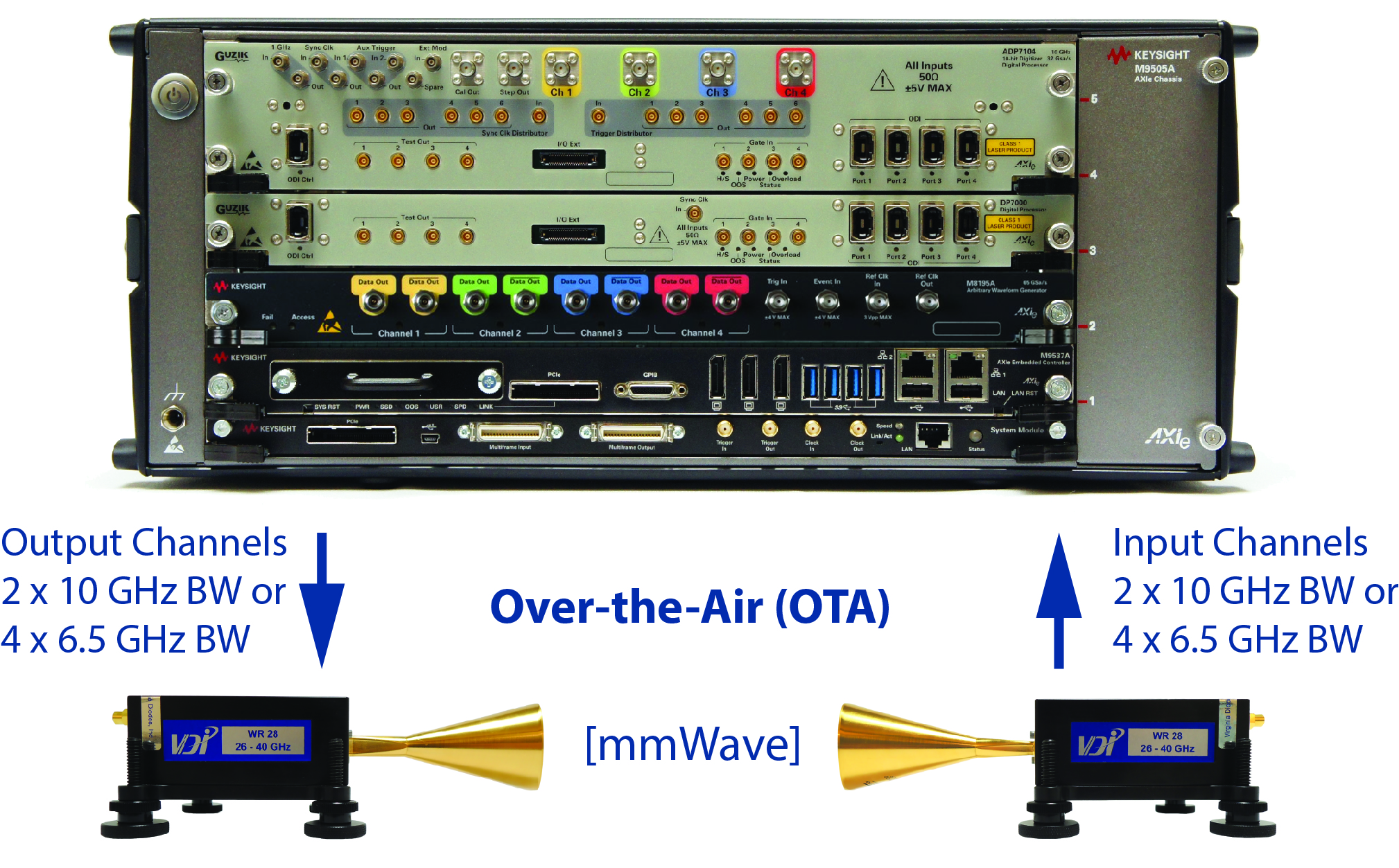
The new generation 5G mobile networks attracts lots of interests and attentions with its aggressive performance goals. 5G will operate at mmWave frequency band with ultra-broad bandwidths and massive MIMO which needs new channel propagation parameter modelling and characterization testing.
The COTS 5G Channel Sounding System (CSS) is used for channel measurements and channel parameter extractions like Channel Impulse Response (CIR), Power Delay Profile (PDP), Angular Information (AoA and AoD) and Doppler Shift.
The CSS works based on 4×4 MIMO with frequency range from 10 MHz to 40 GHz and bandwidth up to 10 GHz. The setup is also applicable to SISO up to 40 GHz, 50GHz to 75GHz or above.
Channel Sounding Hardware
These instruments are used to generate and analyze frequency bands up to 40 GHz with 4×4 MIMO and max 10 GHz bandwidth (Tx is from 10 MHz to 44 GHz with max 10 GHz bandwidth and Rx is from 10 MHz to 40 GHz with max 10 GHz bandwidth).
The overall V-band Channel Sounding Reference Solution block diagram of the system:
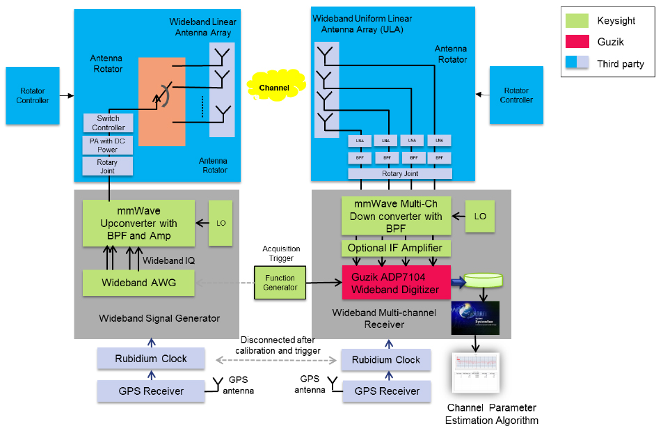
This Reference Solution uses wideband signal correlation with switching at the transmitter and parallel acquisition with the Guzik ADP7104 FPGA-accelerated waveform digitizer receiver.
The waveform digitizer features 10-bit Keysight Analog to Digital A/D converters with sampling rates up to 2 channel 32 Gsa/s and analog bandwidth DC to 10 GHz or 4 channel 16 Gsa/s and analog bandwidth DC to 6.5 GHz with range adjustable front end (-32 dBm to +22 dBm with 1 dB steps). Note block diagram above shows an additional IF Amplifier stage in most cases not required.
ADP7104 has 128 GBytes of acquisition memory standard and delivers the longest waveform capture time window available in a high-performance digitizer.
ADP7104 also features an FPGA-based reconfigurable digital signal processor with up-to real-time processing speed to convey massive time-critical computations directly inside the instrument.
Real-Time Digital Down-Conversion (DDC) with de-embedding equalizer and IF Magnitude trigger
The Guzik ADP7104 10-bit 16/32 Gsa/s digitizer can directly sample RF signals at DC to 6.5 GHz on four channels or DC to 10 GHz on two channels simultaneously and in Real-Time Digitally Down-Convert (DDC) the signals to digital I-Q baseband.
The digital down-conversion FPGA block diagram, equalization filtering, re-sampling and decimation process is shown below:
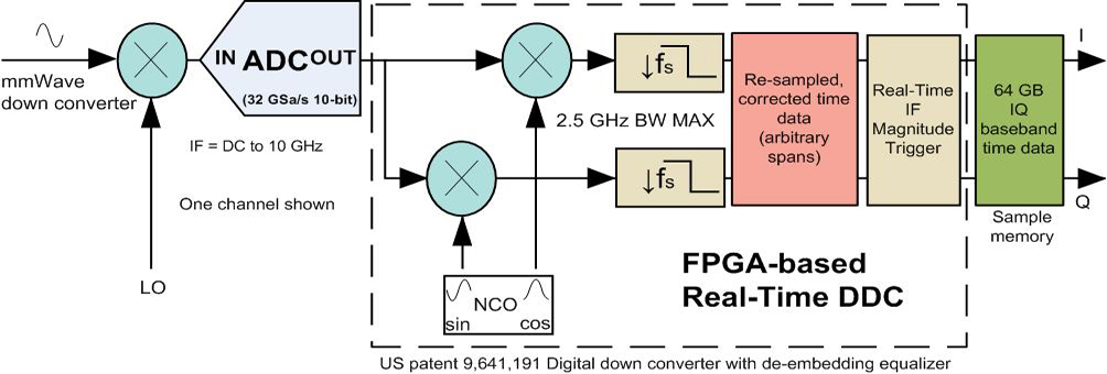
The patented digital down converter with an equalizer translates an ADC output signal to a low frequency spectral region, followed by decimation. All operations of correction of the processed signal are carried out with a reduced sampling rate compared with sampling rates of the prior art. Equalization is performed only in a frequency pass band of the down converter. The achieved reduction of the required computation resources is sufficient to enable the down converter with equalization to operate in a real time mode at up to 32 Giga samples per second (Gsa/s).
The data from the ADC is transferred directly to the DDC with digital equalizer, then to the memory and from memory to the analysis software. The down conversion is implemented by two multipliers with Sin/Cos LO signals. The LO signals area created per channel settable with a 44-bit Numerically Controlled Oscillator (NCO) design inside the FPGA-s and allows to set the DDC center frequency per channel with 0.0018 Hz resolution for 32 Gsa/s and 0.0009 Hz for 16 GSa/s mode.
Down converted signals connected through LPF/decimator to I/Q memory and are then transferred to PC.
Real-Time DDC per channel settable user-span has a 1 Hz setting resolution and has an oversampling factor of 1.28x. For a signal with 1 GHz user-span the DDC output data-rate is 1.28 GSa/s. Each sample pair of I & Q is coded on 16/32 bits (8/16-bit I and 8/16-bit Q). For every user span bandwidth reduction by four, the signal to-noise ratio (SNR) is improved by 6 dB or 1 bit of vertical resolution Effective Number of Bits (ENOB).
The Real-Time IF magnitude trigger allows setting a level the signal needs to achieve at a specified center frequency per channel and allows the data for the signal of interest to pass to the I/Q memory this allows to Start and Stop Variable Length Segments on the IF Magnitude.
In the channel sounding system the signals are down converted with the use of up-front analog down converter to the Intermediate Frequency (IF) within the analog signal bandwidth of the ADP7104. The digital de-embedding equalization technology is extended to external mmWave down-converters which are working together with the wideband digitizer to create a calibrated channel sounding receiver.
Note: ADC_ADDCRT1 option license is required to enable the Real-Time DDC, ADC_BB option license is required to control the de-embedding equalizer and ADC_VSM1 option license is required to enable Variable Length Segment Mode. Maximum supported Real-Time down converter user span for the modulated signal is 2.5 GHz in 16G/32 Gsa/s mode (ADP7104) and 1.56 GHz in 10/20 Gsa/s mode (ADP7084).
The PCI Express Gen 3 link provides fast control access and DMA transfer of the acquired data to the host computer’s GPU and CPU-based processing back-end. The x4 link delivers up to 3.2 GBytes/s data transfer rate in a Gen3 capable AXIe chassis. In addition, four dedicated Optical Data Interfaces can be configured for Real-Time Continuous Streaming to additional DP7000, host PCs or RAIDs at up to 16/32 Gsa/s (80 GBytes/s).
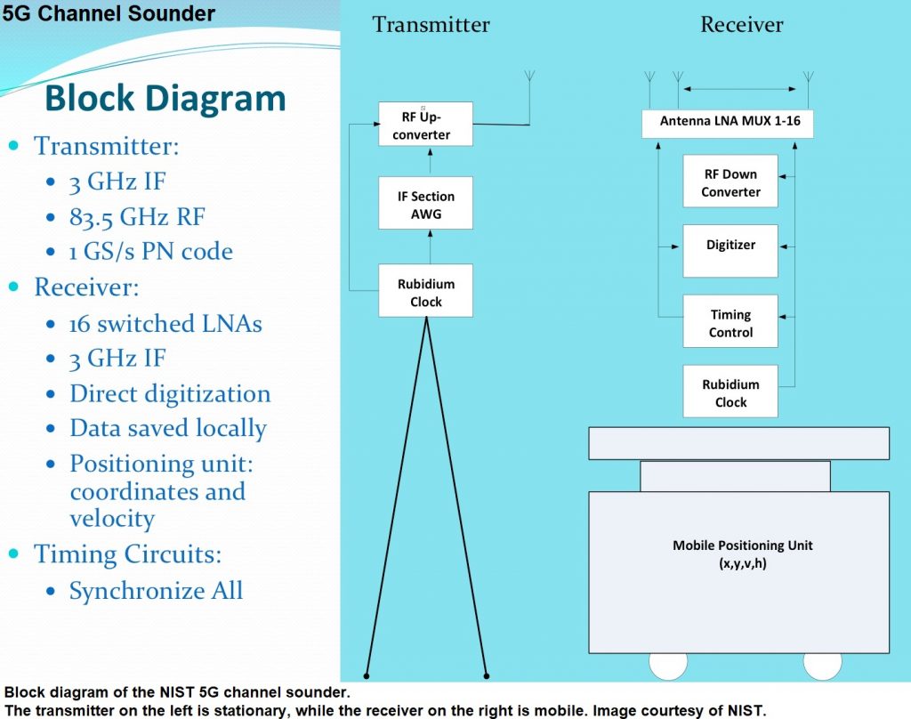
NIST Utilizes AXIe Digitizers for 5G Channel Sounding
National Institute of Standards and Technology | NIST utilized the Guzik Digitizers for their 5G channel sounder project. Learn more…
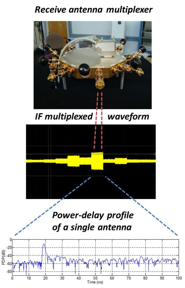
Below please find a demo of fast time-difference-of-arrival (TDOA) cross-channel correlation measurement.
Cross correlation is computed for a repetitive 1uS 4GHz wide linear FM signal between two DC-10 GHz digitizer channels. CH1 is the reference loop-back signal and CH4 signal path goes through a fixed mmWave (28 GHz) up/down converter path.
The resulting correlation function is averaged 50 times every 30 ms shown by “Freq” to increase signal-to-noise (SNR) by reducing additive noise and the resulting correlation between the channels is displayed. The delay between channels is varied on the output of the arbitrary waveform generator (AWG) to demonstrate fast and precise time delay measurement between wideband pulses.
Demo 1:
Demo 2:
Please contact Guzik Technical Enterprises to find out more about the wideband channel sounding solution here: sales@guzik.com

