DOCSIS 3.1 (D3.1) Test Equipment
with ADP7104 and M8190A
- Generate and analyze DOCSIS 3.1 downstream (DS) and upstream (US) coded signals
- Pre-correct waveforms for overall channel response
- Supports many topologies for transmitter / receiver testing (IQ, IF, RF)
- Independent reference to debug and validate hardware performance
- 2 channel RF modulation analysis bandwidths up to 10 GHz (4 channel 6.5 GHz)
- Each digitizer channel has adjustable front-end (-32 dBm to +22 dBm with 1 dB steps)
- Digitizer Full-scale (FS) noise floor down to −160 dBm/Hz
- Frequency bands between DC and 5 GHz with base instruments
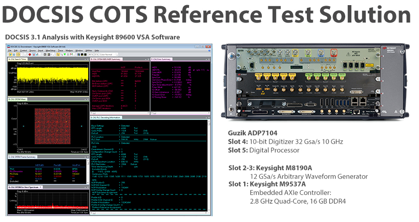
DOCSIS 3.1 Test Equipment
Data Over Cable Service Interface Specification (DOCSIS) standard evolved to meet the needs of cable operators and their subscribers. Emerging applications like 4k video streaming around the home and in-room gaming, is driving demand for multi-gigabit data rates. The need for increased bandwidth led to the latest standard revision – DOCSIS 3.1 Full Duplex provides a way for cable operators to increase capacity and speed and the ability to deliver 10 Gbps in the upstream and 10 Gbps in the downstream on an existing hybrid fiber-coaxial (HFC) network. It’s efficient spectrum use enables a significant decrease in the cost per bit for data delivery. This provides cable operators a competitive advantage over satellite and wireless providers in the hotly contested battle for today’s bandwidth-hungry broadband data subscribers.
The DOCSIS 3.1 Test Equipment allows to generate and analyze multichannel DOCSIS 3.1 waveforms for complete component, subsystem, and system performance at baseband, IF, and RF. This Compact Reference Solution combines COTS modular hardware and software from Guzik and Keysight Technologies, which provides a flexible testbed for DOCSIS 3.1 waveform generation and analysis. With a residual Modulation Error Ratio (MER) measurements 50.0 dB or better. The test setup allows to de-embed external cables, attenuators or amplifiers in front of the digitizer with Guzik patented FPGA-based interleaved ADC amplitude and phase response equalizer.
Software provides the flexibility to generate and analyze DOCSIS 3.1 and previous DOCSIS standard waveforms with a wide range of different attributes and bandwidths.
Modular hardware provides the flexibility to support baseband, IF, and RF test planes. Patented FPGA-based Real-Time Digital Downconversion (DDC) can be used to greatly improve measurement speeds.
Frequencies up to 5 GHz can be generated and up to 10 GHz can be analyzed with the base test equipment configuration for testing with a wide range of IF’s and RF frequencies.
Direct digitizing and Real-Time Digital Downconverting of the input signal eliminates the spectrum artifacts associated with analog down conversion, such as Local Oscillator (LO) feedthrough and greatly improves the VSA 89600 software measurement speed.
This Reference Solution can be used as an independent reference to help debug and validate hardware performance issues as they occur.

DOCSIS 3.1 Measurement Applications and Software
- Keysight N7623B Signal Studio for Digital Video to generate fully coded DOCSIS 3.1 waveforms
- Keysight DOCSIS 3.1 Downstream Modulation Analysis 89600 VSA Software option 89601B/BN-BHM
- Keysight DOCSIS 3.1 configuration wizard to create the OFDM setup files for 89600 VSA custom OFDM (Option BHF) based on the downstream and upstream configurations.
DOCSIS 3.1 Downstream MER Loopback Performance Measurements
MER is the most common metric used to characterize signal quality in DOCSIS Cable Modem Termination System (CMTS) and Cable Modem (CM) testing.
DOCSIS 3.1 downstream 4096 QAM signal at carrier 200 MHz with channel bandwidth 192 MHz (Residual MER 50.47dB)
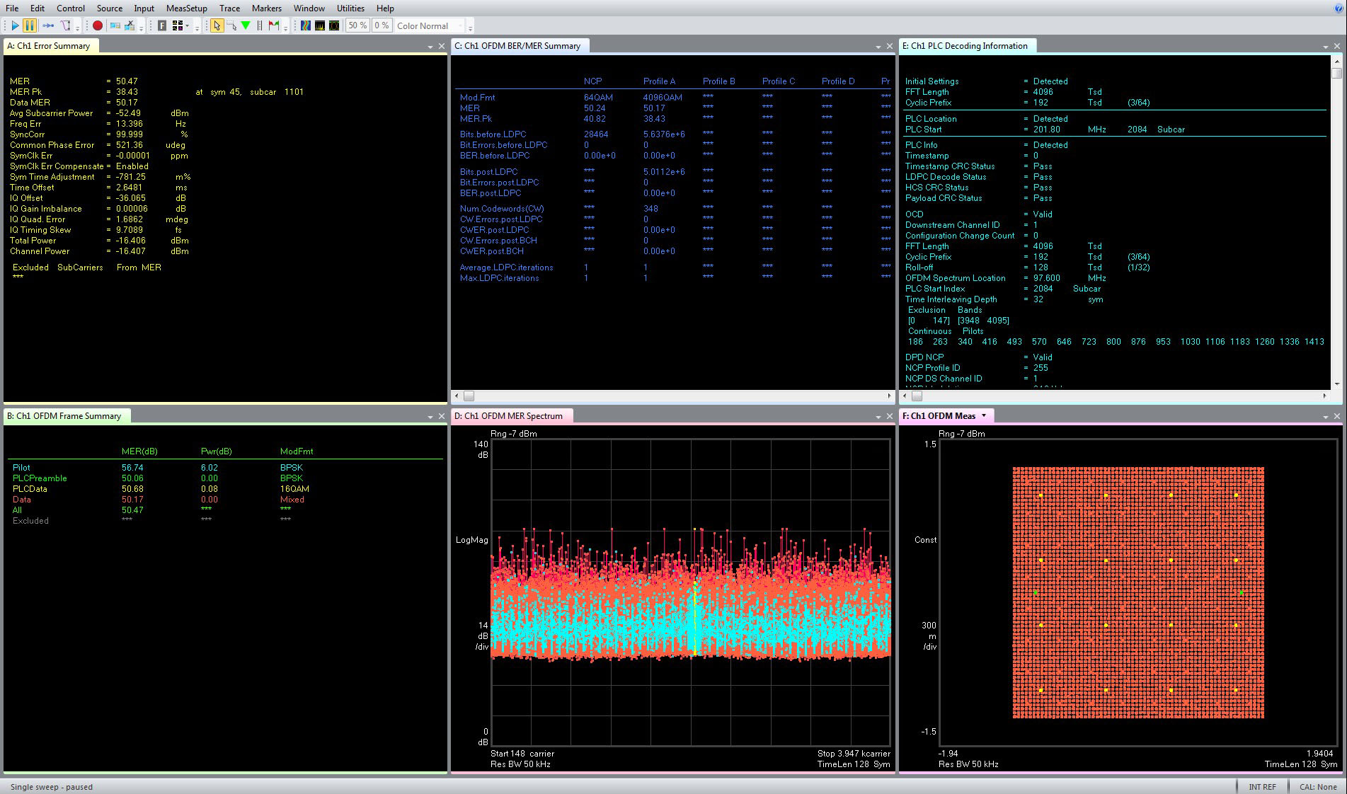
DOCSIS 3.1 downstream 4096 QAM signal at carrier 400 MHz with channel bandwidth 192 MHz (Residual MER 50.66dB)
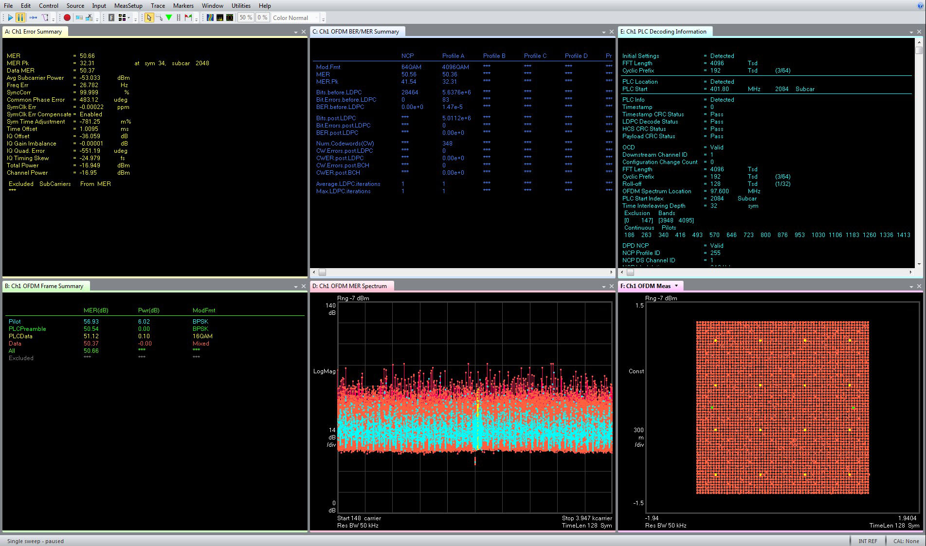
DOCSIS 3.1 downstream 4096 QAM signal at carrier 550 MHz with channel bandwidth 96 MHz (Residual MER 53.06dB)
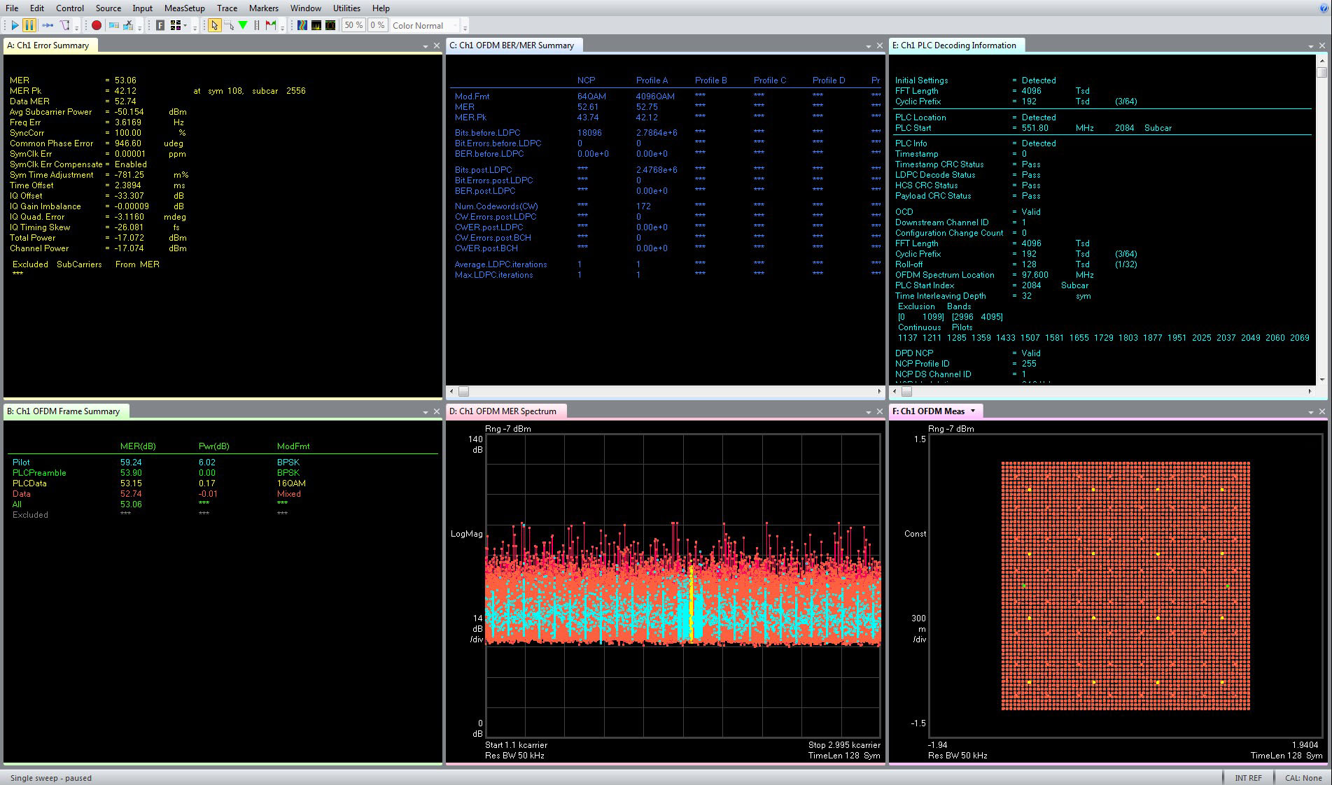
DOCSIS 3.1 downstream 4096 QAM signal at carrier 600 MHz with channel bandwidth 192 MHz (Residual MER 50.37dB)
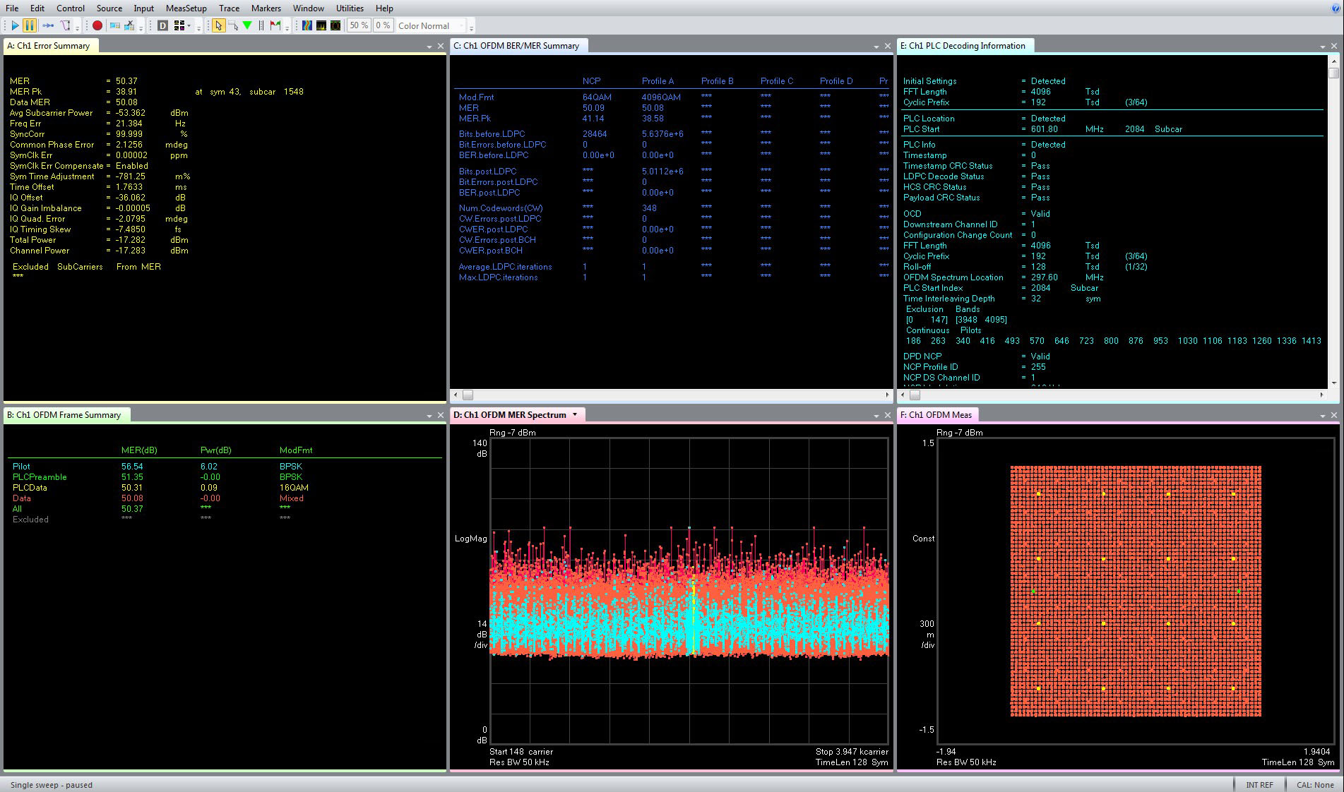
Note: Application Sample measurement results provided are representative and performed under ideal conditions without “Pre-Corrections” at +25˚C ambient temperature. The results are not warranted specifications.
1 Channel Configuration:
The analysis speed greatly depends of the processing capability available to the test solution, either as an integrated measurement personality or as software running internally on a computer connected to signal analyzer. As the DOCSIS waveforms grow in complexity and bandwidth, the traditional signal analyzers have a tough time keeping up with delivering the analysis speed necessary for high-volume manufacturing.
The Guzik ADP7104 Series 10-bit Digitizer is employing techniques similar to most digital radio receivers for decoding digital modulations. The digitizer can directly sample RF signals at DC to 10 GHz on multiple channels simultaneously and in Real-Time Digitally Downconvert (DDC) the signals from any center frequency within the digitizer bandwidth to digital I-Q baseband. This technique provides all digital fast high accuracy repeatable measurements and display of modulation characteristics by reducing both front-end active analog signal chain components and supporting elements. More info here.
With the FPGA-based digital signal processing capabilities in the Guzik ADP7104 Series 10-bit Digitizer, the overall measurement process is accelerated to enable the measurement speed requirements for DOCSIS 3.1 analysis both during R&D and volume manufacturing.
DOCSIS 3.1 downstream loopback measurement time with M8195A AWG and ADP7104 Digitizer with Real-Time DDC.
DOCSIS 3.1 downstream 4096 QAM signal at carrier 2 GHz with channel bandwidth 192 MHz.
MER Measurement Speed ~180ms (BER analysis OFF and MANUAL configuration for the incoming downstream signal):
Trace B: BER/MER Summary.
Trace C: Frame Summary.
Trace G: Error Summary.
Trace J: PLC Decoding Information.
Measurement Speed ~1.2s (BER analysis ON and MANUAL configuration for the incoming downstream signal):
Trace B: BER/MER Summary.
Trace C: Frame Summary.
Trace G: Error Summary.
Trace J: PLC Decoding Information.
Measurement Speed ~1.4s (BER analysis ON and AUTO configuration for the incoming downstream signal):
Trace B: BER/MER Summary.
Trace C: Frame Summary.
Trace G: Error Summary.
Trace J: PLC Decoding Information.
Note: Application Sample measurement results provided are representative and performed under ideal conditions without “Pre-Corrections” at +25˚C ambient temperature. The results are not warranted specifications.

