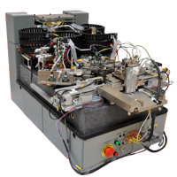
DTR 3000 Spinstand with XY-Positioning
Overview
For Head, Headstack and Disk Testing:
- Embedded Servo with 2–3 kHz bandwidth1
- Servo Accuracy2 4 nm (0.016 µInch), 1 s
- Servo Resolution 02 nm (0.001 µInch), 1 s
- Non-Repeatable Run-out (NRRO) in Servo
mode22 – 0.6 nm (0.008 – 0.024 µInch), 1 s - Positioning repeatability3 of 0.6 – 1.0 nm
(0.024 – 0.039 µInch) Peak-to-Peak deviation of track profile slope - Mounting both up-facing and down-facing heads from the top
- Fast track-to-track seek for Media Scanning applications
- Vacuum and screw clamping disk chucks
- Combloader and Head Stack toolings available
- Crashproof XY-Positioning to protect spindle4
Guzik DTR 3000 XY-positioning spinstand uses the X and Y coarse positioning stages actuated by linear motors and the micro-positioning stage actuated by the piezo element aligned with X coordinate axis to place the tested head on the specified track. WITE32 software converts the requested track number and skew angle into X and Y coordinates.
________________
1 With Piezo-Actuator Cartridge, patent pending
2 With optional Servo Improvement Package
3 Typical parameter value
4 US Patent 7,061,235 B2
Micro-positioning in Servo and Non-Servo Modes
Guzik DTR 3000 spinstand can use one of the two following modes for the head positioning:
- Non-servo mode, when the actuation is done by the piezo element with feedback from the glass linear scale.
- Embedded servo mode, when the actuation is performed by the piezo element, with feedback from the servo bursts written on the same track with the data signal. These bursts are located at the beginning of every sector. Guzik DTR 3000 spinstand supports sector sampling rates up to 50 kHz (20 µs).
Using the servo mode assures high positioning repeatability. The head suspension and some spinstand parts expand when temperature changes during measurements. The embedded servo eliminates the positioning errors caused by this thermal expansion. The spinstand in the servo mode also suppresses low-frequency vibrations transmitted from the floor.
The track profile repeatability observed on the Guzik DTR 3000 spinstand in servo mode is 0.6 – 1.0 nm (0.024 – 0.039 µInch). The typical non-repeatable runout (NRRO), measured as 1 s of the Position Error Signal (PES) from the embedded servo, is 0.2 – 0.6 nm (0.008 – 0.024 µInch). Repeatability and NRRO significantly depend upon the particular head and media used but are consistent for the same head type. The data above was obtained using a 7200 RPM product.
Advanced Linear Scale Interpolator
Guzik DTR 3000 spinstand features an advanced linear scale interpolator developed by Guzik Technical Enterprises. The spinstand with 2 µm period glass scales and the interpolator has measurement accuracy of ±0.3 nm (±0.012 µInch).
Key Features
Guzik DTR 3000 spinstand performs software controlled alignment for each tested head. The alignment procedure takes one second and measures the position of the disk center with accuracy 80 µInch (2 µm). The results can be improved by averaging. The procedure increases the accuracy of track and skew angle positioning. As a result, Guzik DTR 3000 spinstand achieves higher accuracy of WROffset, Writer Width, and Reader Width measurements.
There are no head amplifier boards on the cartridges for Head Loading Mechanism HLM-3000. The new cartridge design has only a small board integrated with a head connector. The head amplifier boards are removed from the cartridges and installed on the swinging platforms of HLM-3000 without sacrificing electrical performance.
Guzik DTR 3000 spinstand can be used for head (HGA, HAA) testing and, after mechanical conversion, for headstack (HSA) testing. Guzik Technical Enterprises offers tooling for specific HGA, HAA, and HSA designs.
Crash-Proof Design
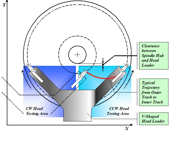
Guzik DTR 3000 is a crash-proof spinstand due to the new patented design of the Head Loading Mechanism HLM-3000. The arms of the V-shaped HLM-3000 are rotated 45 degrees in respect to the X and Y coordinate axes of the spinstand. Such geometrical configuration and the mechanical limit on the movement along the Y axis set the working area over the lower quadrant of a media (see Figure 1). This prevents the cartridge from the collision into the spindle/media when the mechanical parameters of the spinstand or the head geometry are specified incorrectly in the software.
Figure 1: Working Area of HLM-3000
Air Bearing Spindle
- Motor: Brushless DC, programmable 100 RPM – 20,000 RPM
- Interchangeable Spindle Chucks:
- 85″, 1.0″, 1.8″, 2.5″, and 3.0”/3.5″ available
- Vacuum version and screw clamping version
- RPM Jitter: 005% typical
- Acceleration: 0 – 10,000 RPM in approximately 2.4 seconds with 3.5″ disk mounted
- Balancing: Included as standard
- Shroud: Included as standard (two options: automated for media testing or for HGA testing)
Coarse Positioning Mechanism
- Actuator Type: X and Y linear motors
- Movement Type: Simultaneous dependent XY trajectory movement
- Skew Angle Control: Software controlled skew angles
Micro-Positioning Mechanism
- Actuator Type: Piezo element
- Micro-Positioning Encoder Type: Heidenhain glass scale encoder and embedded servo
- Drive Servo: supports Drive Servo for DTR testing
- Guzik Servo: supports Guzik Servo Revision 3 and Revision 4.
- Local Micro-Positioning Accuracy of Glass Scale within Piezo Range: ±0.3nm (±0.012 µInch)
- Position Repeatability: 6 – 1.0 nm / 0.024 – 0.039 µInch typical, measured as maximum deviation of the track profile slope in servo mode (measured at 7200 RPM)
- Non-Repeatable Runout: 2 – 0.6 nm / 0.008 – 0.024 µInch typical, 1 s (measured at 7200 RPM with Piezo-Actuator Cartridge)
- Hysteresis: Closed loop system, no hysteresis
Head Loading Mechanism
- HGA, HAA, and HSA tooling
- Tooling can be designed to custom specifications
Spinstand Electronics
- Separate Control Box and Spinstand Frame for electrical and mechanical noise reduction
- Control Box Type: SCB DTR 3000 control box
- Connection to PC: USB interface
Physical
| Spinstand | Control Box |
| Size: 32″ x 19″ x 17″ | Size: 18″ x 18″ x 8″ |
| Weight: 256 lbs | Weight: 36 lbs |
Operational
- Environmental: 15 C to 40 C, 90% maximum relative humidity, with no condensation, clean room environment
- Power Supply:
110 VAC 15% 50/60 Hz, 3 A approximately
230 VAC 15% 50/60 Hz, 2 A approximately
- Air Supply:
90 PSI minimum, clean dry air
- Air Consumption:
1.6 scfm mass airflow, typical with vacuum chuck
* Specifications are subject to change without notice
Performance Measurements
The Track Profile Plot on Figure 2 demonstrates typical 0.6 – 1.0 nm / 0.024 – 0.039 Inch positioning repeatability of the Guzik DTR 3000 spinstand. Signal was written on the track and the amplitude of the read signal was measured at 5 nm / 0.2 Inch increments across the track. The measurements were repeated 50 times in forward direction, and 50 times in backward direction.
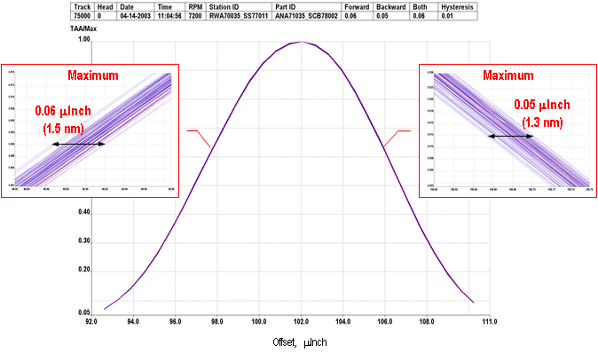
Figure 2: Normalized Track Profile Plot (50 Runs Forward + 50 Runs Backward)
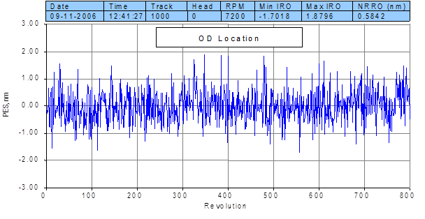
The figures below demonstrate Position Error Signal (PES) measured on DTR 3000 spinstand. Position error signal is derived from servo bursts written on the media in every sector. Each sector delivers one position error value, expressed in nano-meters. PES was captured for 800 consecutive revolutions and plotted in time on Figure 3 and Figure 4.
The standard deviation (one sigma) of PES data in every sector characterizes the non-repeatable runout (NRRO) of the head. The NRRO value shown on the plots below is 0.2 – 0.6 nm (0.008 – 0.024 µInch), measured at 7200 RPM with Piezo-Actuator Cartridge.
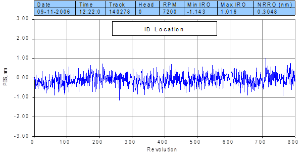
Figure 3: Position Error Signal at ID
