Wide Ka-Band Signal Reference Test Solution
with ADP7104, M8195A, WR12CCU, WR12CCD, N5183B
- Generate and analyze Ka-band (26.5 – 40 GHz) waveforms with up-to 10 GHz of occupied bandwidth
- Pre-correct waveforms for overall channel response
- Supports many topologies for transmitter / receiver testing (IQ, IF, RF, microwave, millimeter-wave)
- Independent reference to debug and validate hardware performance
- 2 channel RF modulation bandwidths up to 10 GHz (4 channel 6.5 GHz)
- Frequency bands between DC and 10 GHz with base instruments
- Frequency bands between 26.5 – 40 GHz with extended millimeter-wave configurations
- Over-the-Air (OTA) measurements using waveguide horn antennas
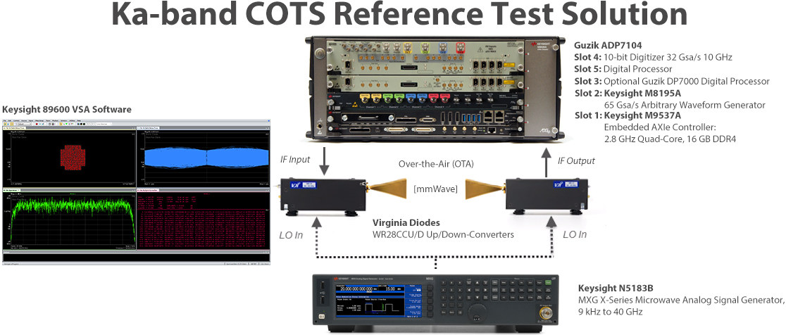
This compact flexible reference solution for Ka-Band, Ka Wide-Band and Ka Super Wide-Band signal analysis combines commercial off-the-shelf (COTS) modular hardware and software from Guzik, Keysight Technologies and Virginia Diodes, which provides a flexible multichannel testbed for E-band waveform generation and analysis. The test setup allows to de-embed external cables, attenuators or amplifiers in front of the digitizer with Guzik patented FPGA-based interleaved ADC amplitude and phase response equalizer.
The setup also allows to use digital pre-distortion (DPD) and adaptive equalization techniques to equalize the measurement channel.
Software provides the flexibility to generate and analyze Ka-band waveforms.
Modular hardware provides the flexibility to support baseband, IF, and millimeter-wave test planes.
Frequencies up to 10 GHz can be supported with the base test equipment configuration for testing with a wide range of IF’s and the 26.5-40 GHz E-Band frequencies can be generated and analyzed with the Virginia Diodes compact up-converters and down-converters.
This Reference Solution can be used as an independent reference to help debug and validate hardware performance issues as they occur.

Signal creation software:
- Keysight flexible IQTools utility application for waveform generation and pre-corrections for Keysight high-speed AWGs and Vector Signal Generators.
Measurement applications and software:
- Keysight 89600 VSA software
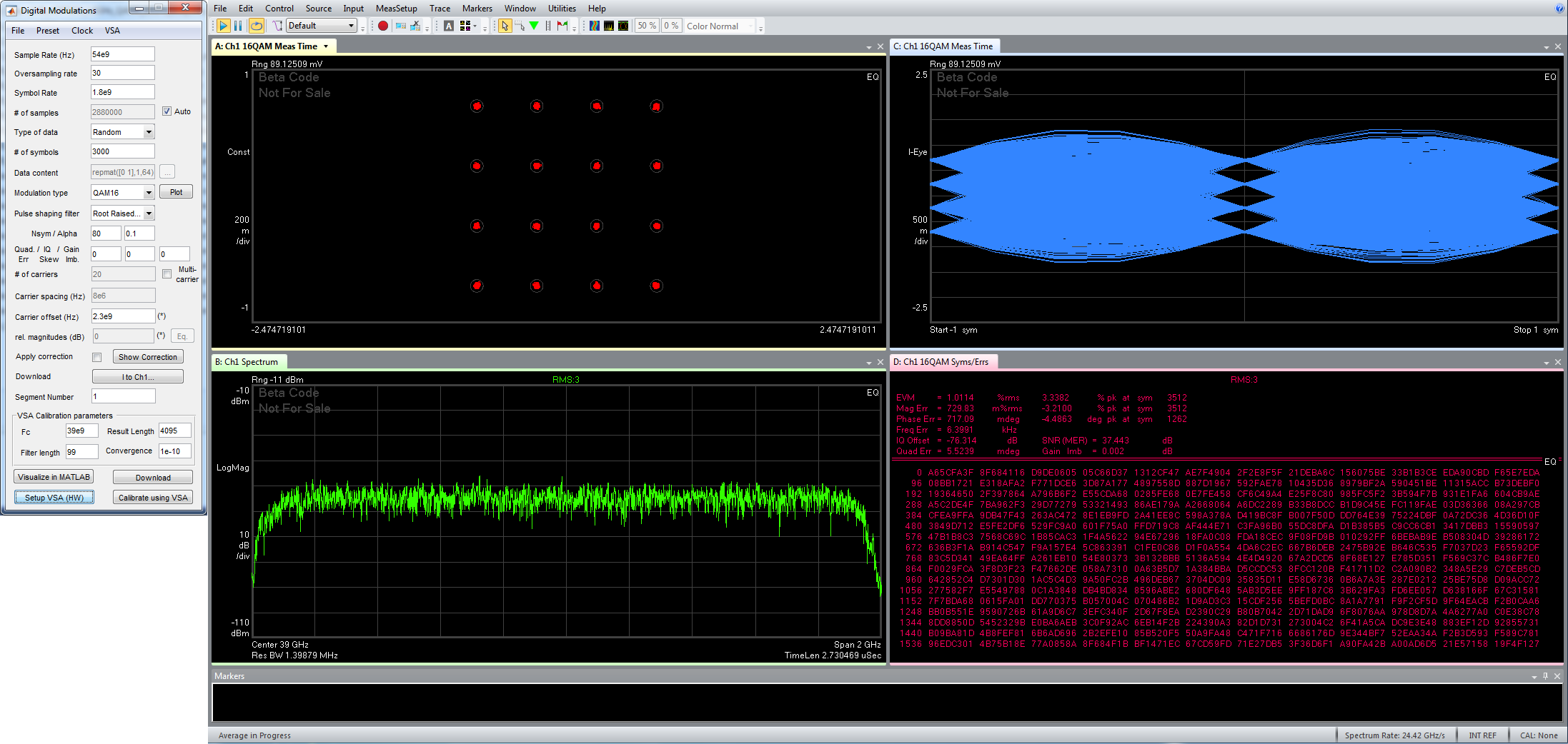
mmWave WR-28 Waveguide Band Reference Setup.
- 26.5-40 GHz isolator
- VDI28.0BPFE37-40 bandpass filter with Insertion Loss < 1 dB
The measurements below in the mm-wave range are performed via waveguide interface WR-28 for simplicity.
Radiated emission over-the-air (OTA) measurements with waveguide horn antennas can lead to high attenuation. Each ADP7104 digitizer channel has adjustable front-end (-32 dBm to +22 dBm with 1 dB steps), which allows to fine tune the receiver for best EVM.
EVM performance at 39 GHz mmWave center frequency (with adaptive equalization).
| Center Frequency | Symbol Rate | Modulation Format | EVM |
| 39 GHz | 1.8 GHz | 4QAM | 1.2% (-38.4 dB) |
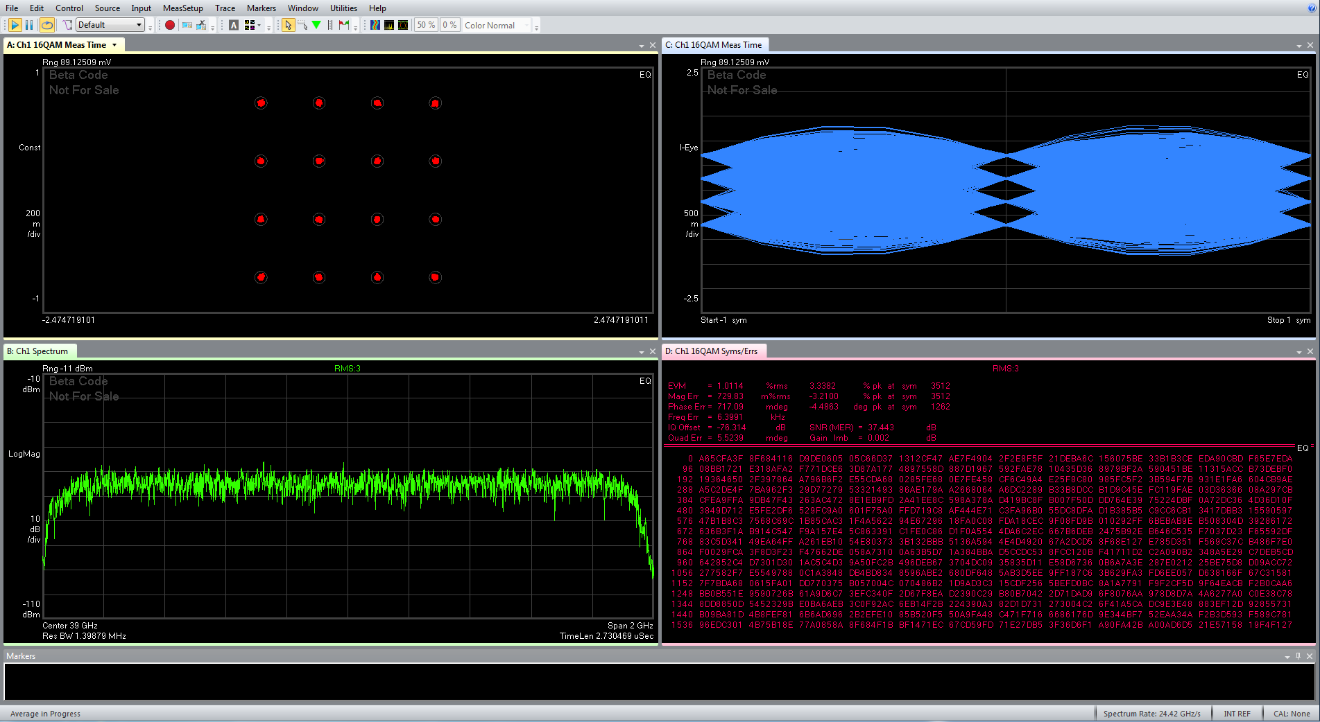
| 39 GHz | 1.8 GHz | 16QAM | 1% (-40 dB) |
| 39 GHz | 1.8 GHz | 64QAM | 0.93% (-40.5 dB) |
| 39 GHz | 1.8 GHz | 256QAM | 0.9% (-40.9 dB) |
| 39 GHz | 1.8 GHz | 512QAM | 0.8% (-41.9 dB) |
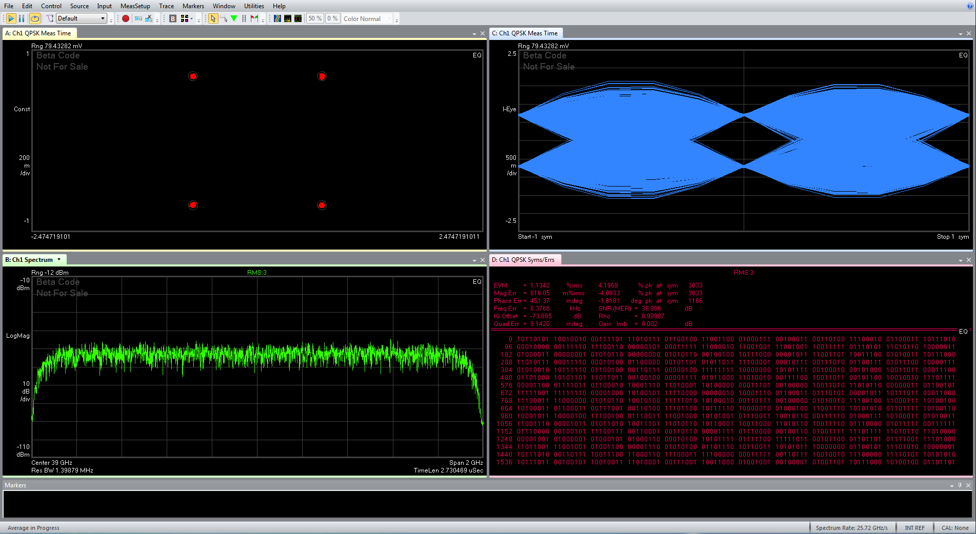
| 39 GHz | 1.8 GHz | QPSK | 1.2% (-38.4 dB) |
Note: The transmit and measurement Root-Raised-Cosine (RRC) filter roll-off factor 0.1. The result length is 4095 symbols and the number of averages is 3.
QAM4 – EVM 1.2% (-38.4 dB)
16QAM – EVM 1% (-40 dB)
64QAM – EVM 0.93% (-40.5 dB)
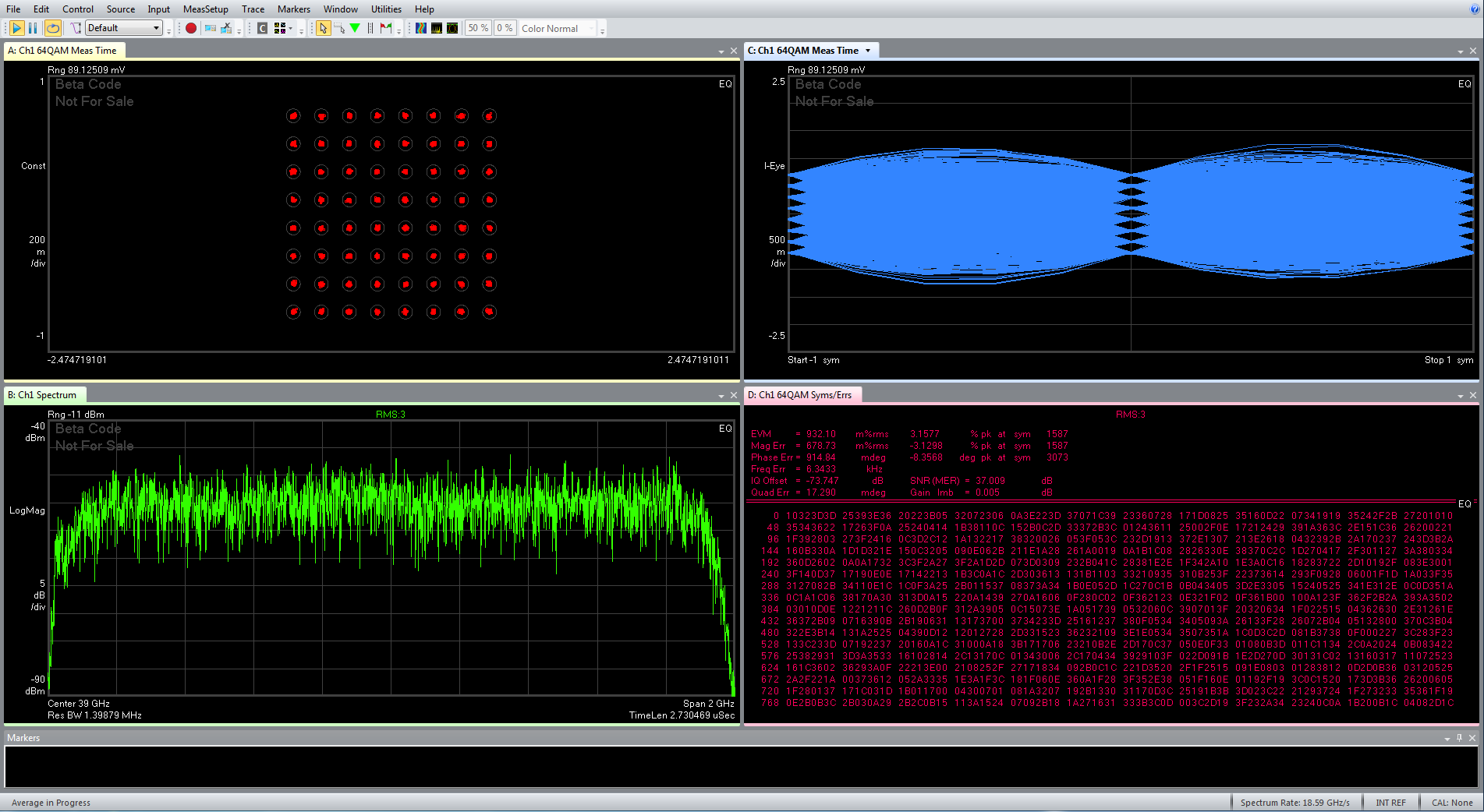
256QAM – EVM 0.9% (-40.9 dB)
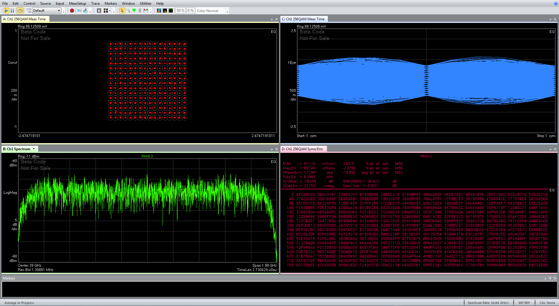
512QAM – EVM 0.8% (-41.9 dB)
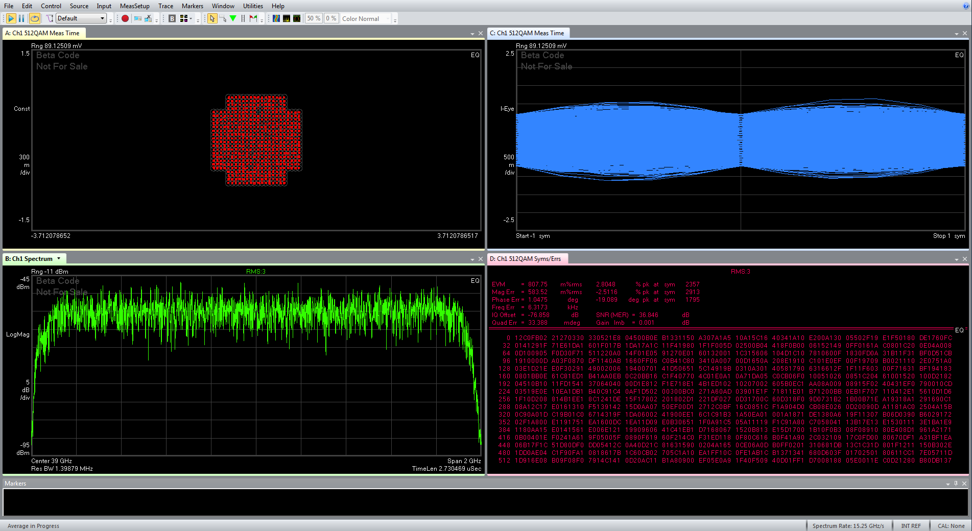
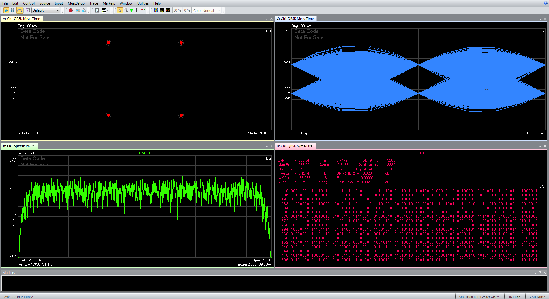
1.8 GHz sample rate Quadrature Phase-Shift Keying (QPSK) modulation EVM performance at 39 GHz mmWave center frequency (with adaptive equalization):
1.8 GHz sample rate QPSK with RRC roll-off factor 0.1 – EVM 1.2% (-38.4 dB)
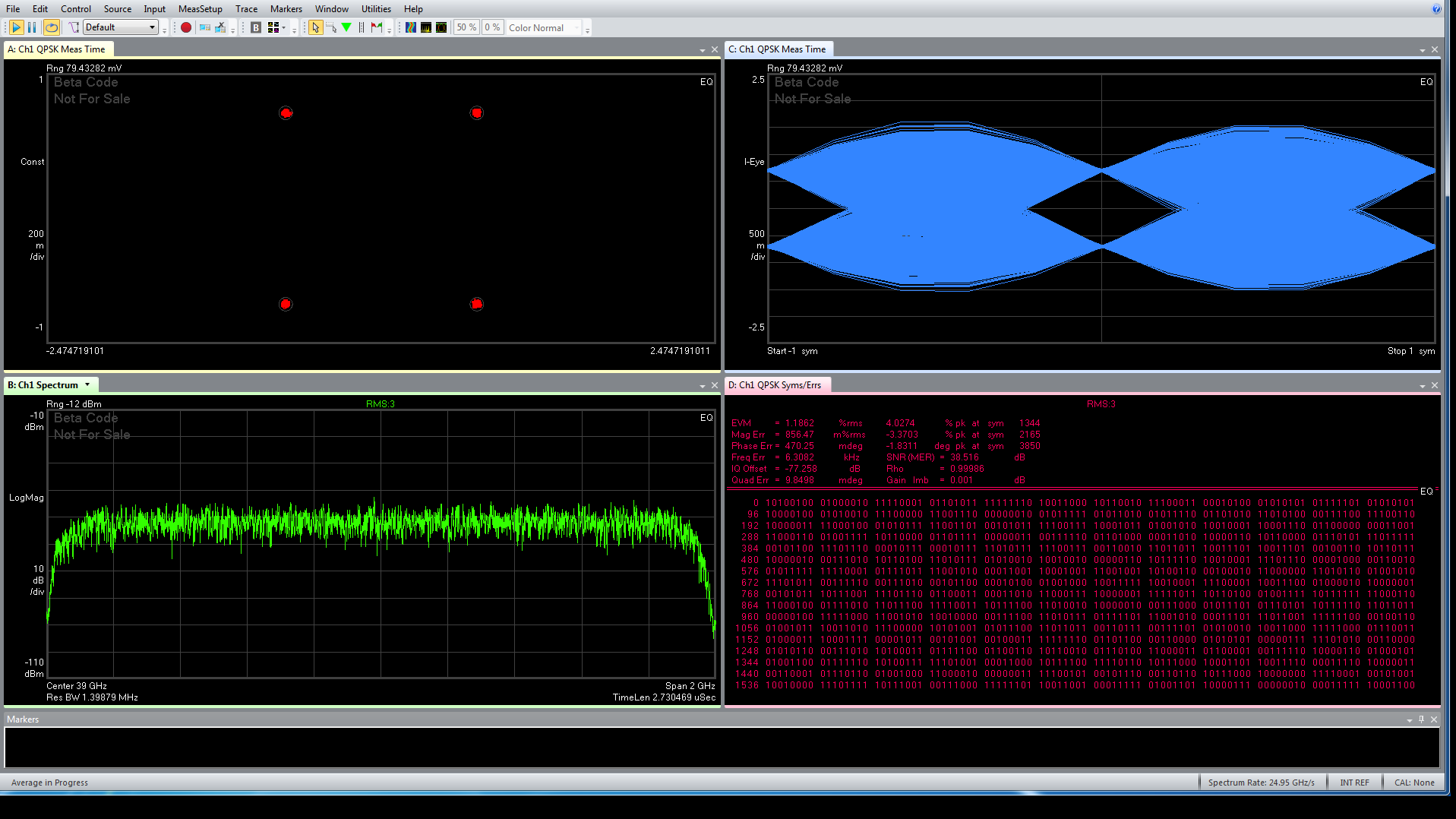
1.8 GHz sample rate QPSK with RRC roll-off factor 0.1 at 2.3 GHz IF center frequency – EVM 0.9% (-40.9 dB)
Note: Application Sample measurement results provided are representative and performed under ideal conditions without “Pre-Corrections”, if not specified otherwise and at +25˚C ambient temperature. The results are not warranted specifications.
1 Channel Configuration:

