Media Scanning Package (MSCAN)
MSCAN Media-Scanning Test for WITE32:
- Scans media and executes selected defect scanners
- Includes PRML scanners for Missing Pulse, Extra Pulse, and Thermal Asperity
- Optimizes skew angle to achieve minimal read-write offset for faster test execution
- Needs 45 min to scan 100,000 tracks with 10 µIn step between tracks (R&D), and less than 2.5 min to scan 1,000 tracks with 1,000 µIn step between tracks (Production)*
- Supports constant linear velocity and constant angular velocity (RPM) modes
- Provides error listing, graphical scanning report, error marking, and defect waveform capturing by oscilloscope
- Features open software interface – users can develop their own modules
- Saves the parameters of all detected errors to a file that can be opened later at the same or a different computer to review the data and generate reports
________________
* Scanning conditions: V2002 spinstand rev.7, RWA 2002, CAI 4K, 10000 RPM, head movement and error detection included
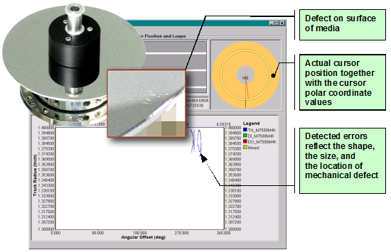
MSCAN Package
The MSCAN package has a modular structure (see Figure 1).

Figure 1: MSCAN Modules
The package consists of the following modules:
The Scan Preparation Test measures the head geometry to determine the read-write offset at all tracks for the MSCAN
The MSCAN Test scans media for defects.
Spinstand Control Modules:
- For Guzik V2002 spinstand
- For Canon spinstand
Media Scanners:
- Marvell 7500P for CAI 4K*
- Marvell 7500M for CAI 4K*
- Marvell 7500P for CAI 2K
- Marvell 7500M for CAI 2K
- Agere RC6600 Redtail for CAI 2K
- Agere MS552 Diamondback** for CAI 2K
________________
* Using CAI 4K is recommended, because this chip adapter has faster data transfer speed and accelerates media scanning. Some existing ANA units of RWA 2000 series, however, may require an upgrade for CAI 4K. Please contact sales@www.guzik.com.
** This type of PRML chip has been discontinued. The option is available for the customers, who have the Diamondback chip adapter. Some existing Diamondback chip adapters may require an upgrade. Please contact sales@www.guzik.com.
Error Processors:
- Graph Engine displays an interactive dialog box with all errors. You can zoom in on any error to see its size and location.
- Surface Report displays and prints a media outline with the locations of all detected errors.
- Error Listing displays and prints a list of all found errors and the error coordinates in the sector and byte, time from index, and angle from index coordinate systems.
- Error Tagging marks errors on media by writing special patterns before and after each error.
- Error Capturing takes a screenshot of every error with a digital oscilloscope, prints it, and saves to a file.
Graph Engine
The Graph Engine error processor has two dialog boxes:
- The Graph Engine dialog box (see Figure 2) shows a map of the detected defects and allows you to zoom in and zoom out at any location on the scanned tracks for the desired level of details when browsing the defects on the media.
- The Test Results dialog box shows a track-by-track table of defects with the quantity and the types of the defects detected on each track.
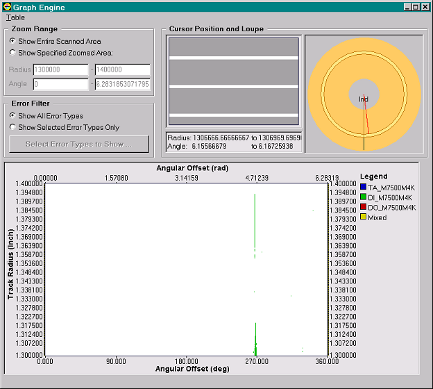
Figure 2: Graph Engine Dialog Box
Surface Report
The Surface Report error processor generates a report displaying a media outline with all detected defects marked by different symbols (see Figure 3). The processor prints an actual-size outline of the media showing the error locations. It also has the option of saving the report as a bitmap file.
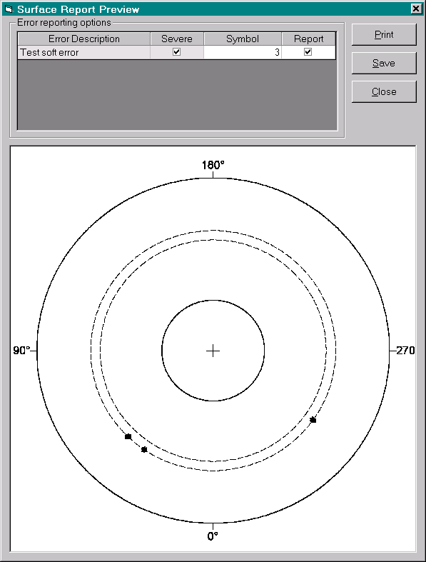
Figure 3: Surface Report Preview Dialog Box
Error Listing
The Error Listing processor saves information about the detected errors to a file using the comma-separated value (CSV) format. The saved data can be loaded to MS Excel or other spreadsheet program or database, so you can use third-party software to analyze information reported by the MSCAN test (see Figure 4).

Figure 4: Error Listing Imported to Microsoft Excel
Error Tagging
The Error Tagging error processor does in-track marking of the defects detected by a media scanner. For the in-track marking, the processor writes the selected pattern before and after every single defect or every group of defects (see Figure 5).
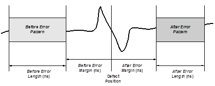
Figure 5: Error Tagging Diagram
Signal Capturing
The Signal Capturing error processor captures the signal waveforms from a digital oscilloscope and prints the waveforms as a report (see Figure 6). In the report you can see the read-back signal at the moment, when a media scanner detects an error. The processor can also save this report as a bitmap file.
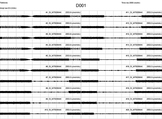
Figure 6: Signal Capturing Report
- Guzik V2002 or Canon spinstand
- Guzik RWA 2000 series or 2585/2550 series with CAI 4K* or CAI 2K
- WITE32 version 3.30 or later
- MSCAN software license (contact sales@www.guzik.com to obtain a quotation)
________________
* Using CAI 4K is recommended, because this chip adapter has faster data transfer speed and accelerates media scanning. Some existing ANA units of RWA 2000 series, however, may require an updgrade for CAI 4K. Please contact sales@www.guzik.com.

