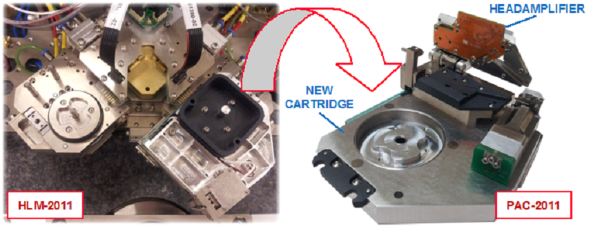
New Headloading Mechanism HLM-2011 and High Data Rate Cartridge PAC-2011
- Headamplifier on a cartridge for improved Write and Read channel performance – closely emulates the HDD internal HSA arrangement
- Guzik proprietary pneumatically controller coupling* with headloader HLM‑2011 platform for improved mechanical stability
- PAC-2011 Piezo-Actuator Cartridge with AE Sensor
- Design allows for additional devices to be mounted on top of the cartridge, such as laser optics for HAMR
- Crash-proof V-shaped HLM*
________________
* This product is protected by US patents 7,836,605 and 7,061,235
Guzik introduces a new front-end to its Spinstand Models V2002 and DTR 3000, which includes new Headloader Mechanism HLM-2011, new cartridges PAC-2011, and new Universal Preampilifer UP11.
The new cartridge design improves read and write channel performance for high data rates. It has been achieved by using only one set of high frequency pogopins between headamplifier IC and HGA. See Figure 1 for the new arrangement, where the headamplifier IC is on the PAC‑2011 Cartridge. Figure 2 shows the existing arrangement, where the headamplifier IC resides on the headamplifier board mounted on the HLM-V2002 Headloader.

Figure 1. Interconnection in New HLM-2011 and PAC-2011 with HGA Device Under Test (DUT).

Figure 2. Interconnection in Existing HLM-V2002 Design with HGA Device Under Test (DUT).
It is well known that in 100 Ohm differential impedance environment pogo pins are working well beyond 10 GHz. The reason is that pogo pins with inductance in fraction of nH do not create significant impedance mismatch with 100 Ohm differential interconnection.
The same inductance is very critical in connection to low HGA writer impedance (about 5 Ohm). In the new design the head is connected to the headamplifier through one set of short, high frequency and low inductance pogo pins in order to improve write performance. Moreover, headamplifier IC is located as close to the head as possible, as shown in Figure 1.
BER Measurements
BER Measurements with existing and new front-end were performed in two locations with the following data rates:
- 1855 Mbit/s at OD, radius 44.4mm, and
- 1320 Mbit/s at MD, radius 28.0mm.
The BER results are shown in the table below:
| Head # | New front-end | Existing design | ||
| OD | MD | OD | MD | |
| 1 | 10E-4.7 | 10E-6.04 | 10E-4.03 | 10E-4.92 |
| 2 | 10E-5.99 | 10E-6.01 | 10E-4.96 | 10E-5.99 |
Performance Measurements
The eye diagram was measured using a fixture and the setup shown in Figure 3. A 5 Ohm resistor was soldered instead of the write head at the end of HGA flex.

Figure 3. The Eye Diagram Measurement Setup
The same HGA flex circuitry and head equivalent was used for existing design measurements.
Figures 4-11 show the eye-diagrams for new and regular headamplifier designs. The eye-diagram in Figures 4, 6, 8, and 10 show significant performance improvement over regular design in Figures 5, 7, 9, and 11:
- The new design has wider bandwidth and fewer reflections. Rise/fall time is approximately 53ps for the new design and 60ps for the regular design. As a result, on the 3 Gbit/s eye diagram we can observe full amplitude overshoot with a flat top. In the regular design overshoot does not reach full amplitude and has different levels as a result of superposition with different level of reflected signal. At 4Gbit/s, we can see similar effects – in regular design overshoot becomes even smaller and we can see inter-symbol distortions (wider transition zone).
- In both designs, eye diagram is quite open. For communication systems, this would be sufficient to achieve high performance. However, in disk drives, we are always working on the slope of the write-read frequency response. Therefore, the small degradation of write current response significantly affects system performance. This is why we observe one order of magnitude BER improvement even for relatively low data rates.
Measurements at 3Gbit/s
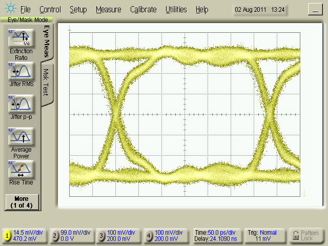
Fig 4. New front-end, 3GB/s, pattern PRBS X12+X6+X4+X1+1, no overshoot
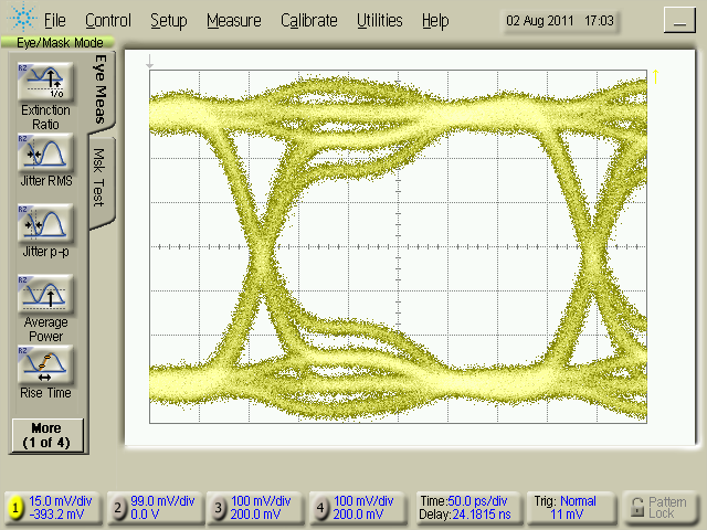
Fig 5. Regular front-end, 3GB/s, pattern PRBS X12+X6+X4+X1+1, no overshoot
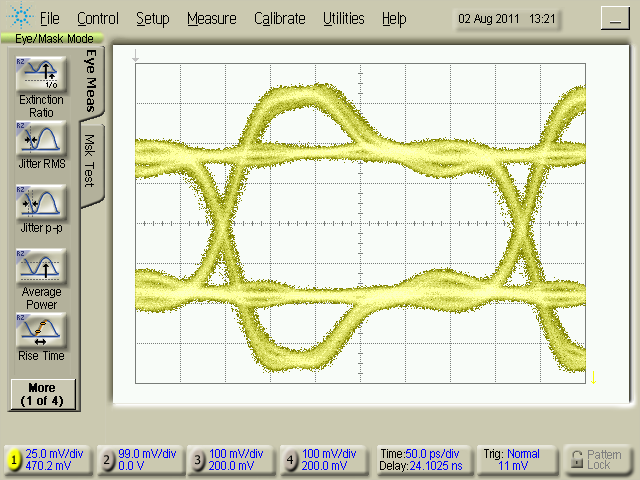
Fig 6. New front-end, 3GB/s, pattern PRBS X12+X6+X4+X1+1, with overshoot
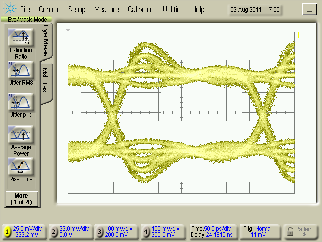
Fig 7. Regular front-end, 3GB/s, pattern PRBS X12+X6+X4+X1+1, with overshoot
Measurements at 4Gbit/s
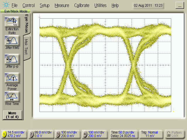
Fig 8. New front-end, 4GB/s, pattern PRBS X12+X6+X4+X1+1, no overshoot
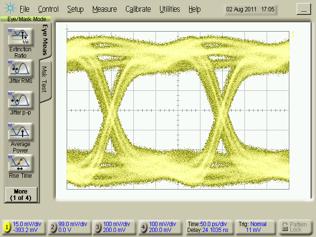
Fig 9. Regular front-end, 4GB/s, pattern PRBS X12+X6+X4+X1+1, no overshoot
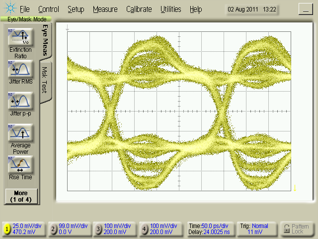
Fig 10. New front-end, 4GB/s, pattern PRBS X12+X6+X4+X1+1, with overshoot
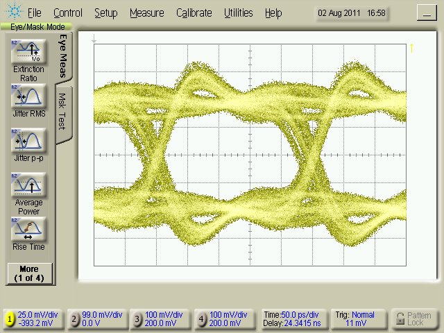
Fig 11. Regular front-end, 4GB/s, pattern PRBS X12+X6+X4+X1+1, with overshoot
System Upgrade Requirements
- RWA System 4000 Series, RWA 3000 DTR Series, or RWA 2000 Series
- Guzik Spinstand DTR 3000 all revisions, or V2002 revision 16 and up.
- DTR or V2002 Spinstand Control Box with ColdFire® Microprocessor revision T and higher.
- WITE32 Revision 4.40 or greater
Upgrade Kit
Upgrade for existing systems includes:
- New Headloading Mechanism HLM-2011
- New Headamplifier Interface
- New Cartridge with the Headamplifier
- New Combloaders
- Universal Preamplifier 11 (UP11)
Please contact sales@www.guzik.com to obtain a quotation for upgrade. An active software maintenance and support contract is required to upgrade to WITE32 Revision 4.40.


