Optical Scales Correction for Guzik Spinstand S1701B – Obsolete
-
Better Test Results Repeatability on Different Spinstands
-
Up to Three Times Better Spinstand Positioning Accuracy
-
Up to Two Times Better Accuracy of W/R Offset Measurements

The Optical Scales Distortion Correction developed by Guzik Technical Enterprises measures the repeatable component of the optical scale position error and compensates for this component. The correction effectively linearizes the scale position feedback. The linear, non-distorted position readings from the optical scales are extremely important in the precise head geometry measurements including W/R Offset, Write Width, and Read Width tests.
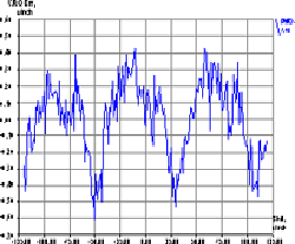
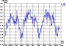
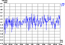
The plot on Figure1 shows how the W/R Offset* changes when the track location moves across the optical scale within the scale period. The repeatable components of the scale distortion are clearly visible. The error caused by this distortion can be as big as ±0.5 µInch. The Figure2 represents the results of the same W/R Offset* measurements but with the correction applied. The repeatable component is suppressed, and the maximum error is less than ±0.25 µInch.
 Figure 1: W/R Offset without Correction** |
 Figure 2: W/R Offset with Correction Applied** |
Why Distortion Correction?
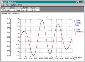
The accuracy of the spinstand micro-positioning is limited by the accuracy of the position encoders. The common problem of all optical encoders is the non-linearity of the scale position readings across the effective diapason of the scale. This non-linearity has the repetitive component with the period of the optical scale. The magnitude of the periodic component dominates over all other distortions and can be as big as 1% of the scale period, well above the position noise caused by the scale reader. For the scale with 80 µInch period on Figure3 the maximum position error can be as big as ±0.4 µInch (±0.2 µInch typical).
The position reading inaccuracy causes the error in the head micro-positioning. This in turn reduces the absolute accuracy of the Write-to-Read Offset and head geometry measurements and leads to the poor result correlation on different spinstands. The non-linear distortion of the scale feedback leads to the distortion of the track profile measurement. Moreover, track profiles built on two tracks written with some small position shift (i.e. in the different scale period phase) will have dissimilar distortions, producing the different head geometry measurement results.
The effect can be observed in the following situations:
- The spinstand performs a reset operation. The operation changes the scale period phase of the reset position. This, in turn, leads to the different scale period phase on the tested track. So, the two track profile measurements performed on the same track before and after the spinstand reset vary.
- The same head has been tested on different spinstands. It is impossible to find two optical scales with the same position distortion. This results in dissimilar track profiles distortions for different spinstands, so the head geometry measurement results diverge.
The Optical Scales Distortion Correction is distributed as a WITE32 external module called Scale Correction test. The test is available for Guzik 1701B spinstands starting from WITE32 Version 2.70.
The Scale Correction test requires a license based on the RWA and Spinstand serial numbers. To obtain the license, call the Guzik Technical Enterprises sales department.

Figure 3: Optical Scale Periodic Distortion of Position Readings
________________
* The values of the W/R offset are measured when the track is written with different offsets from some initial location.
** X-axis shows track offsets from an initial location, Y-axis shows W/R offset delta (µInch).

