Wideband Pulse Radar Test Solution
with ADP7104, M8195A, WR15CCU, WR15CCD, N5183B
- Generate and analyze pulse radar waveforms
- Pre-correct waveforms for overall channel response
- Supports many topologies for radar transmitter / receiver testing (IQ, IF, RF, microwave, millimeter-wave)
- Independent reference to debug and validate hardware performance
- 2 channel RF modulation bandwidths up to 9 GHz (4 channel 6.5 GHz)
- HF, VHF, UHF, L-, S-, C-, and part of X-band radar frequency bands between DC and 10 GHz with base instruments
- X, Ku, Ka, mm, V and W radar frequency bands between 8 – 110 GHz with extended millimeter-wave configurations
This Compact Reference Solution combines commercial off-the-shelf COTS modular hardware and software from Guzik, Keysight Technologies, KJ Microwave and Virginia Diodes, which provides a flexible multichannel testbed for radar waveform generation and analysis.
Segmented memory acquisitions in the Guzik digitizers use a circular acquisition buffer with minimum inter-segment dead-time of 300ns. This allows, for example, to capture up to 64 million repetitive radar signals with relatively large repetition intervals. Real-time digital down conversion DDC with frequency and phase response equalization option combined with variable length segmented memory acquisition allows for segmented capture where each segment has a length optimized to capture radar pulses using the Real-Time IF Magnitude Trigger and achieve minimal dead time capture possible. Down to femtosecond resolution time-tagging allows to know the precise time between each captured radar pulse. The test setup allows to de-embed external cables, attenuators or amplifiers in front of the digitizer with Guzik patented FPGA-based interleaved ADC amplitude and phase response equalizer.
The ADP7104 digitizers have excellent frequency response and phase response critical for wideband radar signal capture. Patented group delay measurement is coupled with patented digital equalization [1][2] to create a calibrated baseband receiver with know amplitude and phase response in DC -10 GHz band with input signal range from -32 dBm to +22 dBm.
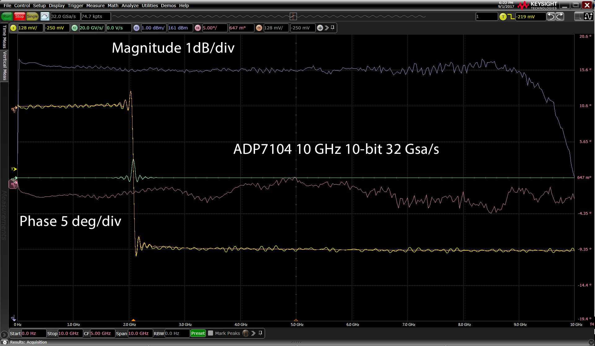
- US Patent 7,408,495 Digital Equalization of multiple interleaved Analog-to-Digital converters
- US Patent 9,933,467 Group Delay Measurement Apparatus and Method
Software provides the flexibility to generate and analyze radar waveforms with a wide range of different attributes.
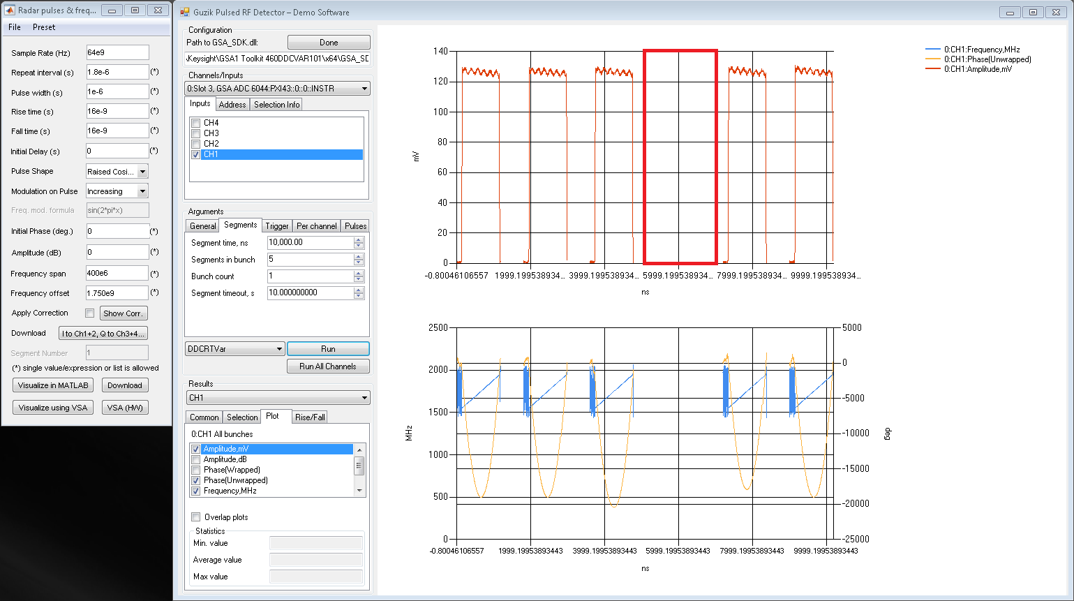
- Guzik Pulsed RF Detector Software sample program with source code is using the GSA_SDK and allows to specify pulse parameters to capture only pulses of interest for visualization. The SDK provides accelerated standard pulse measurements like rise/fall-time, PRF, PRI etc.
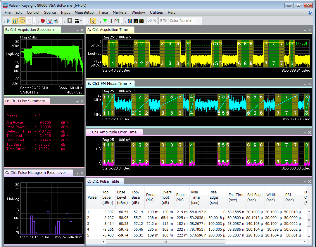
- Pulse signal modulation characteristics and impairment errors can be visualized in detail with multiple time-synchronized amplitude, phase, and frequency (FM) trace results, in addition to flexible trace overlay support with the VSA 89600 Software 89601B/BN-BHQ Pulse Analysis Option. All key pulse signal modulation performance indicators relating to power, droop, overshoot, ripple, time (rise/fall/width/PRI), frequency, phase, and FM modulation can be verified using the comprehensive Pulse Table tabular result metrics. Statistical variance performance data can be quickly viewed for each reported pulse metric, accumulated over single or multiple acquisitions, using the Pulse Cumulative Statistics Table, graphical histogram, and trend line trace plots. Deeper insights into the signal’s time and frequency domain dynamic and spurious performance can be obtained with powerful and flexible trace views such as spectrogram and cumulative history.
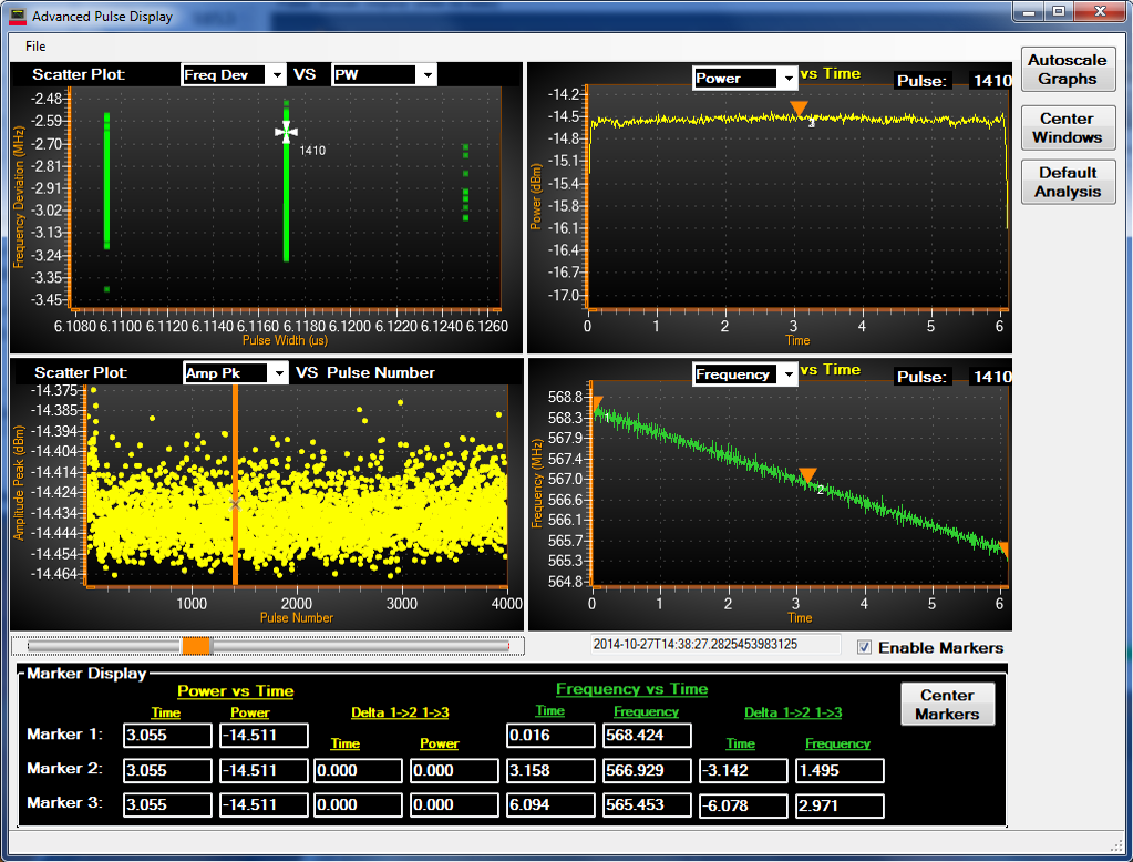
- Keysight Pulse Descriptor Word Collector Software (PS-X10-100) is a radar focused analysis package for measuring signals that change frequency over time and creating PDWs as an output.
Modular hardware provides the flexibility to support baseband, IF, microwave and millimeter-wave test planes.
Frequencies up to 10 GHz can be supported with the base test equipment configuration for testing with a wide range of IF’s. The direct RF-sampling capabilities of the digitizers cover radar signals in HF, VHF, UHF, L-, S-, C-, and part of X-band. Direct RF-sampling reduces the overall system complexity by eliminating several input analog down-conversion stages. The 8-110 GHz X, Ku, Ka, mm, V and W-Band frequencies can be generated and analyzed with up-converters and down-converters from our partners. KJ Microwave AXIe up-converters and down-converters cover 3.2 GHz – 19.2 GHz. Virginia Diodes compact up-converters and down-converters cover 22.5 GHz – 110 GHz.
This Reference Solution can be used as an independent reference to help debug and validate hardware performance issues as they occur.
Measurement applications and software:
- Keysight Signal Studio for Pulse Building N7620B
- Guzik Pulsed RF Detector Software sample program
- Keysight 89600 VSA software with 89601B/BN-BHQ Pulse Analysis Option
- Keysight Pulse Descriptor Word Collector
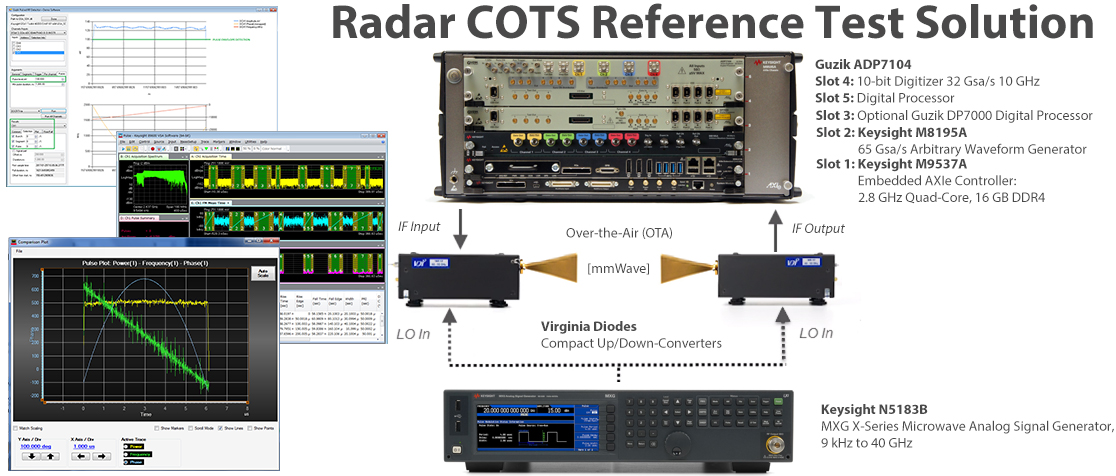
WR-15 Waveguide Band Reference Setup.
- WR15CCU 50-75 GHz Compact Up-Converters (CCU)
- VDI15.0AMP-0055/0067-15-20 Amplifier Band 55-67 GHz, Gain ~17 dB
- VDI15.0BPFE57.24-65.88 bandpass filter with Insertion Loss < 1 dB
- WR-15 Waveguide, V-band Attenuator
- WR15CCD 50-75 GHz Compact Down-Converters (CCD)
The measurements below in the mm-wave range are performed via waveguide interface WR-15 for simplicity.
Radiated emission over-the-air (OTA) measurements with waveguide antennas can lead to high attenuation. Each ADP7104 digitizer channel has adjustable front-end (-32 dBm to +22 dBm with 1 dB steps), which allows to fine tune the receiver for best SNR.
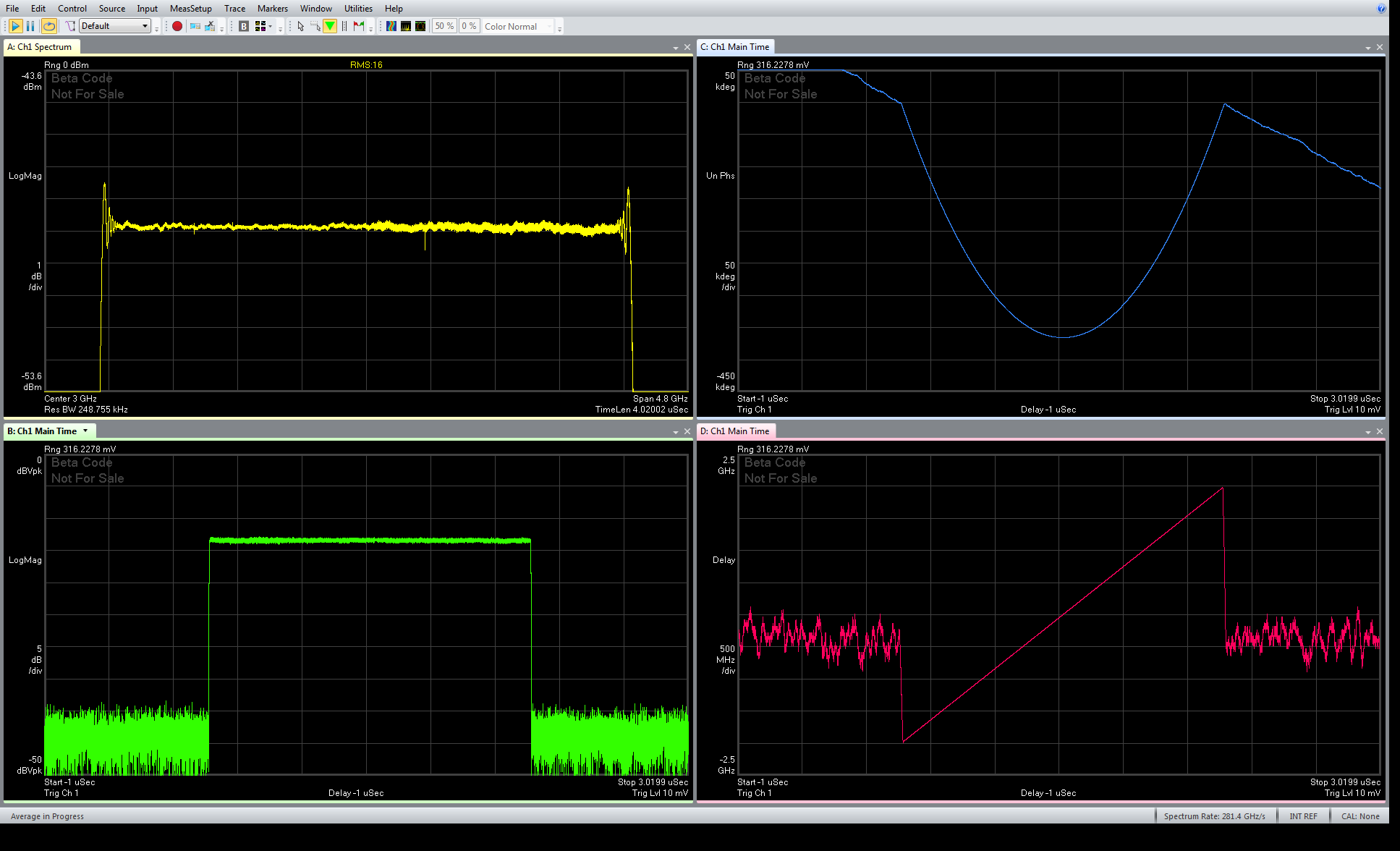
4GHz wide 2 microsecond LFM chirp IF performance (with pre-corrections):
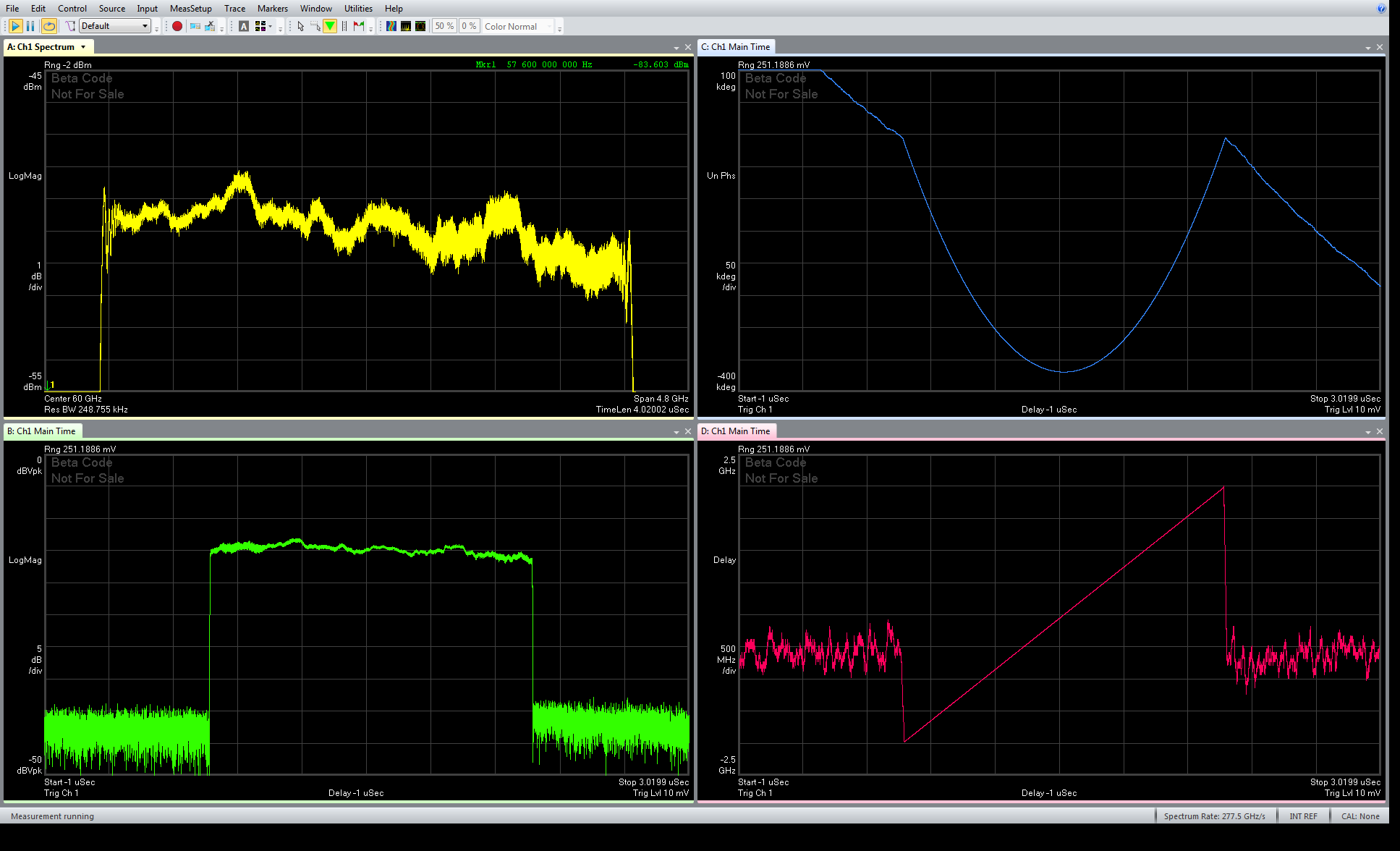
4GHz wide 2 microsecond LFM chirp at mmWave 60 GHz center frequency performance:
4GHz wide 2 microsecond LFM chirp mmWave statistical analysis with VSA 89600 Software Option BHQ:
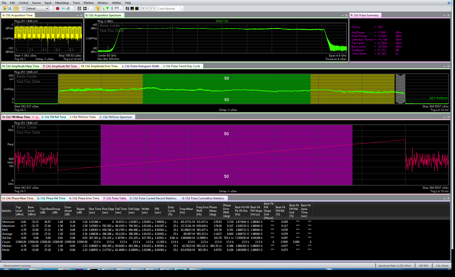
Note: Application Sample measurement results provided are representative and performed under ideal conditions without “Pre-Corrections” at +25˚C ambient temperature. The results are not warranted specifications.
Below please find a demo of fast time-difference-of-arrival (TDOA) cross-channel correlation measurement.
Cross correlation is computed for a repetitive 1uS 4GHz wide linear FM signal between two DC-10 GHz digitizer channels. CH1 is the reference loop-back signal and CH4 signal path goes through a fixed mmWave (28 GHz) up/down converter path.
The resulting correlation function is averaged 50 times every 30 ms shown by “Freq” to increase signal-to-noise (SNR) by reducing additive noise and the resulting correlation between the channels is displayed. The delay between channels is varied on the output of the arbitrary waveform generator (AWG) to demonstrate fast and precise time delay measurement between wideband pulses.
Demo 1:
Demo 2:
1 Channel Configuration:
Please contact Guzik Technical Enterprises to find out more: sales@guzik.com

