Guzik – Magnetic Recording Systems and Measurements Chapter 7
Presenting three first sections of Chapter 7 "Perpendicular Recording" from Alex Taratorin's book "Magnetic Recording Systems and Measurements"
Chapter 7. Perpendicular Recording
- 7.1 Perpendicular recording principles
- 7.2 Write head and perpendicular recording media
- 7.3 Read-back of perpendicular signal
- 7.4 Non-Linear Transition Shift (NLTS) and Hard Transition Shift (HTS) in perpendicular recording
- 7.5 Stray fields and sensitivity to adjacent tracks magnetization
- 7.6 Underlayer noise
- 7.7 Skew angle erasure
- 7.8 Structure of perpendicular track and adjacent track interference
- 7.9 PRML targets for perpendicular recording
- References

7.1 Perpendicular recording principles
7.1.1 Longitudinal and Perpendicular Recording Principle
The difference between longitudinal and perpendicular recording is the orientation of the media grains. In the case of longitudinal recording the grains magnetization is lying in the plane of the magnetic medium. When the media is magnetized by the recording head, the average magnetization is pointing in the down-track direction (Figure 7.1). When perpendicular head and media are used, the media grains are oriented in the “depth” of the medium and their magnetization is pointing either “up” or “down”.
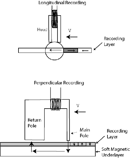
Figure 7.l Comparison of longitudinal and perpendicular recording schemes
The change of the medium magnetization direction seems to be a relatively minor modification of the basic magnetic recording principle. However, this modification changes almost every component of the disk drive design: recording head, magnetic media and detection channel.
Assume that the read sensor is flying over recorded media. The GMR element is sensitive to the vertical component of the magnetic field. In the case of longitudinal recording, the maximum vertical field is generated at the transition location by fringe fields of the magnetic media (Figure 7.2). The read-back voltage resembles a pulse, located at the transition and disappears in the uniformly magnetized area of the longitudinal media. In the case of perpendicular recording, the head is sensitive to media magnetization, therefore the uniformly magnetized media region generates constant read-back voltage of a given polarity in the read sensor. The polarity of the voltage changes when the direction of media magnetization is reversed. Therefore, the read-back signal for perpendicular media consists of voltage steps and resembles a square wave.
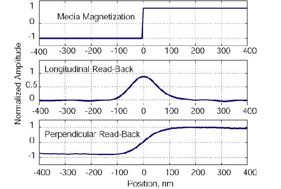
Figure 7.2 Comparison of isolated read-back pulses for longitudinal and perpendicular media
The spatial (or time) derivative of a perpendicular read-back signal closely resembles waveforms obtained with a longitudinal medium (Figure 7.3). In fact, a simple way to utilize perpendicular components in a disk drive is to put a signal differentiator circuit in the read-back path. The signal on the differentiator output is similar to longitudinal read-back and the rest of the signal detection can be adapted from standard longitudinal hardware.
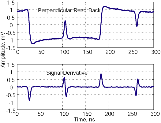
Figure 7.3. Example of derivative of perpendicular read-back signal
Certainly, nature does not like abrupt changes, and the transition from one magnetization direction to another has a finite extent, i.e. the read-back voltage step is not infinitely sharp due to media transition width and read head resolution. Therefore, when higher density is recorded, the adjacent read-back steps are overlapping and the perpendicular signal resembles a sine wave, similar to a longitudinal recording system. The amplitude of the read-back signal drops at higher recording densities, resulting in a roll-off curve, similar to the roll-off observed in longitudinal recording.
7.1.2 Why go to perpendicular?
The answer is simple: nobody knows for sure. The history of perpendicular recording started many decades ago, almost simultaneously with longitudinal recording. Many attempts have been made to develop a perpendicular recording system, however the industry was successfully introducing new generations of longitudinal components, achieving high areal density. The development of high density systems required complicated optimization of recording heads and media, consuming efforts of large groups of scientists and engineers. The few parts, which were produced never demonstrated any advantages over longitudinal recording components. The research in perpendicular recording was left to several university groups and was not considered to be worth much of attention.
The situation changed several years ago (around 2000), when it became clear that the potential of longitudinal media was about to be exhausted due to the superparamagnetic limit (Chapter 3). In order to achieve higher recording densities, the media noise should be scaled down. The standard approach to reducing media noise is to make grains smaller (the transition noise, or irregularity is determined by the particular pattern of grains, switching at the bit boundary). The smaller magnetic grains (average grain diameter below 7-9 nm) become unstable due to thermal fluctuations. The energy barrier of the isolated magnetic grain is defined by the ratio of KuV/kT, where Ku is the anisotropy constant, V is the grain volume, k – the Boltsmann constant and T – temperature. As we have discussed in Chapters 2 and 3, the only way to maintain thermal stability is to use higher anisotropy media. However, this media has high coercivity and can not be written by modern recording heads due to the limitations of the write head materials.
The longitudinal medium grains are oriented in the plane of the magnetic thin film and their diameter determines the recording layer thickness and the grain volume. However, the perpendicular magnetic medium grains are grown in a vertical direction. Therefore, they may have small in-plane diameter D and large volume, forming cylindrical-like columns (Figure 7.4). The ratio of the in-plane diameter D to the grain height t can be about 5:1, supposedly resulting in low media noise and high thermal stability. This simple argument immediately results in an optimistic prediction of approximately 5x density gain of perpendicular recording medium over longitudinal.
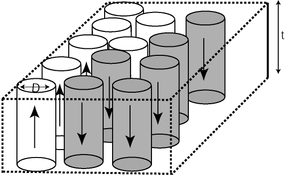
Figure 7.4 Structure of cylindrical grains in perpendicular recording media
As the technology progressed, it has become clear that the thermal stability gains are smaller than expected, but there are many other, less evident advantages of the perpendicular recording scheme.
Here is a partial list of the advantages of the perpendicular recording system over the longitudinal recording, which will be considered in this chapter:
- Higher thermal stability can be achieved by small in-plane grain diameter with cylindrical grain structure.
- A vertical pole head in a recording media with a soft underlayer can generate twice the field of longitudinal recording head.This allows writing higher coercivity medium, further decreasing grain size and maintaining media thermal stability.
- The read-back signal amplitude from perpendicular medium with soft underlayer is larger compared with equivalent longitudinal medium, improving signal-to-noise ratio.
- Perpendicular media grains are strongly oriented. This results in smaller medium noise and a sharper recorded transition. The high orientation of the perpendicular medium also improves side-track writing and edge noise.
- The demagnetization field in the perpendicular medium is small at the transition region. This allows writing narrower magnetic transitions and improves thermal stability of high density data (this is opposite to longitudinal medium). Also, the non-linear transition shifts in the perpendicular medium are less critical, compared with longitudinal recording.
- The track edges in perpendicular medium are less noisy and better defined due to the vertical pole head configuration. Sharp track edges allow higher track density and a smaller bit aspect ratio.
However, as the perpendicular recording components were developed, numerous disadvantages were discovered. Here is a list of some of the disadvantages of the perpendicular system:
- Vertical pole heads have a relatively poor write gradient. Also, the pole write head geometry creates distortions when the head is skewed relative to the track direction. There are also indications that thin pole heads often exhibit pole remanence problems (magnetic domains in the pole tip).
- Perpendicular media with soft underlayer (SUL) develops SUL noise, generated by domains. This requires complicated media biasing schemes in order to eliminate SUL domain walls.
- Read-back resolution of perpendicular recording medium is lower compared with longitudinal medium due to the presence of SUL.
- Both write and read processes are very sensitive to stray magnetic fields and to the magnetization of adjacent tracks.This creates sensor saturation and transition shifts in the recorded data, depending on the magnetization of adjacent data tracks.
- Propagation of magnetic flux in the SUL and thick return pole causes demagnetization of adjacent tracks, increasing the adjacent track interference problem.
The numerous theoretical predictions and experimental evaluations of the perpendicular recording potential are all over the place. The most optimistic scenarios predicted that the optimized perpendicular system may achieve a factor of 4-5 over the best longitudinal areal density, resulting in approximately 500 Gb/in2. Pessimistic evaluations consider that the advantages of the perpendicular recording are compensated by the disadvantages, resulting in the complete wash-out between the longitudinal and the perpendicular schemes. The realistic estimates are in the range of doubling the areal density achievable with longitudinal media, around 200-300 Gb/in2.
The longitudinal transitions are created by the down-track components of the fringe field of the recording head, emanating from the write gap (Figure 7.1). In order to achieve perpendicular magnetization, different write head and media structures are required (Figure 7.5).
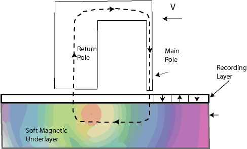
Figure 7.5 Perpendicular recording head and media structure
The maximum vertical field component is achieved by the “pole” head design. The vertically oriented magnetic flux propagates from the head pole into the magnetic medium. The recording layer in this case is in the path of the flux propagation and has predominantly vertical orientation.
The magnetic flux lines have to be continuous, therefore the flux has to propagate through magnetic medium and return to the write head return pole. This is achieved by introducing soft magnetic underlayer (SUL), made of high permeability material. The SUL serves as the return path for the magnetic flux. In this sense, perpendicular media is very different from longitudinal, the SUL becomes part of the recording head. The SUL material, thickness and separation from the write pole have to be optimized taking into account the write head structure and dimensions. Therefore, the proper choice of head/media combination for the perpendicular recording becomes a critical issue.
The structure of perpendicular pole head with soft underlayer provides an immediate advantage of perpendicular recording over longitudinal: The magnitude of the recording field in this configuration is increased by approximately a factor of 2 over longitudinal medium.
This increase of the field magnitude can be understood by assuming infinite permeability of the SUL. In this case, the currents in the write head, generating the vertical magnetic field, create a mirror “image” in the SUL, which can be modeled by a second imaginary write head (Figure 7.6).
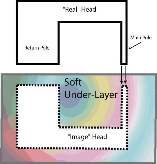
Figure 7.6 Ideal write head imaging in the SUL
As a result, the head vertical field doubles, or, equivalently, the amount of write current, required to generate magnetic field in the head gap is about one half of the current required for generating the same field in the equivalent longitudinal recording scheme.
Typically, the maximum fringing field, developed in the longitudinal ring head is about 2pMs, where Ms is the saturation magnetization of the head material. The maximum vertical field, developed by a pole head in magnetic medium with high permeability SUL is about4pMs.
A higher recording field is very advantageous for magnetic recording. Not only does the cylindrical structure of perpendicular medium grains provide better thermal stability, the ability to overwrite high coercivity medium allows higher anisotropy and improves thermal stability even further. Also, the higher coercivity medium has a smaller transition parameter and allows recording at higher linear density.
A straightforward argument from the vertical field estimate is that the perpendicular pole head can in principle write media with twice the coercivity of the longitudinal medium. However, the realistic gain is much smaller due to different switching processes of longitudinal and perpendicular media. Longitudinal grains have larger dispersion of easy axis orientation and are easier to switch, while perpendicular grains are typically well oriented in the vertical direction. In practice, the coercivity gain of a perpendicular recording system over longitudinal medium may be close to 50-70%.
There are numerous issues related to the choice of optimal pole head geometry and media structure. A typical pole-head geometry is schematically shown in Figure 7.7. The main recording pole (trailing pole) can have a different shape (square, rectangular or trapezoidal). It is characterized by pole width W, pole thickness (PT) and throat height (TH). The recording gap G is the distance between the main pole and the return pole. The leading (or return pole) has a certain thickness (RT).
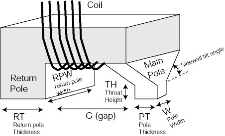
Figure 7.7 Three-dimensional representation of the pole head
The recording medium is characterized by the recording layer thickness, distance between recording layer and the soft underlayer and the thickness of the soft under-layer. Each of the head and media parameters influences the recording process.
A throat height (TH) is the narrowest part of the magnetic flux loop. For a smaller TH the pole tip is close to the narrowest soft core point, where the saturation occurs and the larger vertical field is developed by the head. However, for a short TH, the magnetic charges are generated on the tilted head walls above the main pole. As a result, the write field gradient is degraded and more “side fringing” field is generated. Therefore, TH and side wall angle are optimized in order to achieve a trade-off between the highest achievable write field and the best write field gradient. Generally, the write field gradient of a vertical pole head is 15-25% smaller compared with the gradient of the longitudinal head, however this disadvantage is compensated by the different behavior of the demagnetization field in the perpendicular medium.
Large pole thickness (PT) is advantageous for achieving higher write fields. However, thick pole causes recording problems at the skew angle (an angle between the main axis of the recording head and the track direction). Therefore, the poles are usually designed to be rectangular or have trapezoidal shape.
Shielded pole heads are becoming popular in perpendicular recording. The idea is to place a high permeability shield next to the recording pole. This shield “sucks” some of the head flux and improves the head gradient, while slightly reducing the deep gap field. The shielded head has an additional advantage – a larger horizontal magnetic field component helps to switch perpendicular media.
The flux, emanating from the trailing pole should be able to penetrate the SUL and to flow freely into the return pole. This requirement determines that the SUL should have sufficient thickness and high permeability. CoFeB alloys are usually utilized for SUL materials. The write gap has to be adjusted to the distance to the SUL and SUL thickness. Typical SUL thicknesses are on the order of 100-300 nm. SUL material and thickness are optimized for a particular pole head design. There is also an exchange breaking layer (EBL) between the recording media and the SUL. The EBL layer reduces exchange interactions between the recording layer and the SUL. The EBL layer should be relatively thin, on the order of tens of nanometers in order to reduce overall perpendicular media thickness.
7.3.1 Perpendicular Transition Shape and Field Cancellation Effect (FCE)
The GMR read element is sensitive to the perpendicular component of a stray field, emanating from the recording medium. For longitudinal magnetic recording, the stray field is maximum at the magnetic transition region (Figure 7.8), resulting in the read-back pulse, centered at the transition location.
For perpendicular medium, a well-defined square-wave read-back signal is expected, since the output of the GMR sensor is proportional to the medium magnetization level (Figure 7.2). In reality, the situation is more complicated.
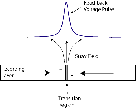
Figure 7.8 Structure of media stray field and read-back pulse for
longitudinal recording
A typical average read-back from low density transitions, recorded on perpendicular medium with SUL is shown in Figure 7.9. As seen, the read-back voltage level is close to a square wave, but is not exactly rectangular.
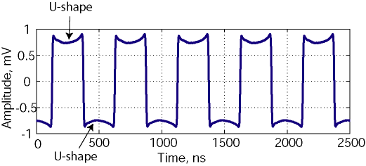
Figure 7.9 Experimental average read-back signal from perpendicular
medium with SUL
A characteristic “bending” of the positive and negative signal levels is evident for both polarities of the transition. Thus “U”-shape is not a measurement artifact, it is generated by the physics of the perpendicular system read-back.
To understand the “U”-shape, we have to analyze the structure of the stray fields in the case of perpendicular recording. The schematic diagram of these fields is shown in Figure 7.10.
As seen from Figure 7.10, the field is zero at the transition location (opposite to longitudinal recording, where the maximum of the stray field is centered at the transition). Outside the transition region, stray field magnitude is not uniform. The maximum stray field is concentrated in the neighborhood of the magnetic transition. At larger distances from the transition center, the magnitude of the magnetic field becomes smaller. Therefore, the GMR sensor read-back signal drops, resulting in the “U’-shape, shown in Figure 7.9.
The vertical stray field reduction is explained by Field Cancellation Effect (FCE). The net stray field, emanating from the media, is created by two layers of magnetic “charges” in the recording media (Figure 7.10). The top layer of the equivalent charges is concentrated at the surface of the media. The bottom layer is generated at the bottom of the soft under-layer (assuming the SUL has infinite permeability). The magnetic field of the medium is the difference between the field, generated by the top and the bottom charges.
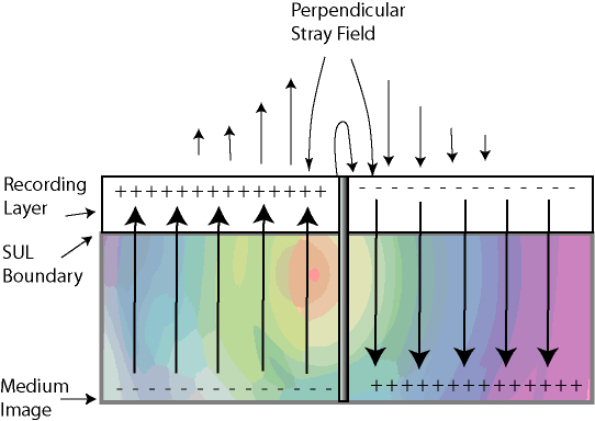
Figure 7.10 Media stray fields for perpendicular media with soft under-layer
If the total medium thickness is relatively small (compared to the distance between adjacent transitions), the top and bottom charges generate similar magnetic fields with amplitude close to the “uniformly charged plane”, equal to 2pMs. The net stray fields from the top and bottom plane will almost cancel each other. Therefore, the stray field between the transitions becomes very small, and the “U-shaped” read-back signal will drop to zero. If recording medium is thick, the contribution of the bottom layer will become smaller and the “U-shape” bending will become smaller, approaching a rectangular square-wave.
The shape of the perpendicular recording signal read-back also depends on the track width. The narrower the recorded track, the less is the Field Cancellation Effect (FCE) and the read-back waveform is closer to rectangular. This is easily understood from the fact that for perpendicular recording media both down-track and cross-track directions are equivalent (they are perpendicular to the medium magnetization direction).
It is therefore expected that for narrow tracks and high recording densities, the read-back signal will become similar to a square wave. For low density transitions and relatively wide tracks, the “U-shaped” signal bending is natural. As we will see later in this chapter, the absence of the “U-shape” for a particular polarity of magnetization indicates non-linear saturation of the read sensor.
7.3.2 AC coupling and signal acquisition
The natural “U-shape” bending of the perpendicular transition read-back is often confused with the limitations of the signal acquisition system.
The majority of modern signal amplification and detection devices (amplifiers, probes, oscilloscopes) are not sensitive to the DC components of the signal. Usually, the constant DC (direct current) component of the signal does not carry any information, only the signal changes are important.
The frequency response of the read-back amplifiers depends on the particular model. The MR5 amplifier, utilized by Guzik test electronics, has the cut-off frequency around 100 KHz. This means that the signal variations, which occur on the time scales larger than 10 microseconds are “filtered” out by the read-back electronics.
Commercial read-back amplifiers usually have low-frequency cut-off at several MHz. This means that time scales on the order of fractions of microseconds are already distorted by the frequency response of the read-back system.
The practical implications of the read amplifier frequency response are the distortions of the read-back signal shape. These distortions resemble the intrinsic “U-shaping”, caused by the intrinsic structure of the media magnetic fields. The higher the amplifier low cut-off frequency, the less of the DC (rectangular read-back regions) components are retained in the signal (Figure 7.11).
However, even the best available amplifiers can not sustain DC levels. Therefore, the exact magnetization level of the magnetic medium is “filtered out” from the read-back signal. An illustration of this effect is shown in Figure 7.12. A simple experiment is undertaken here: a square wave pattern is written in the beginning of the track and the rest of the medium is magnetized to the positive DC saturation levels. The read-back trace corresponds to a media DC noise, caused by local granular structure. The noise trace should ideally remain at the constant positive and negative DC level. Due to field cancellation effect, some “U-shape” bending of this noise trace is expected. However, the frequency response of the read amplifier eliminates the DC component. The model response of the 100 kHz amplifier to the step of voltage is shown on the bottom trace. It can be seen that both traces have similar time-domain response.
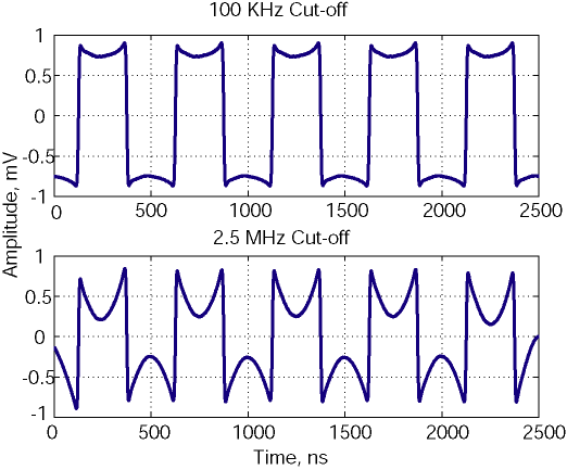
Figure 7.11 Read-back of low density perpendicular square wave pattern
with different LF cut-off frequency: Signal shape distortions
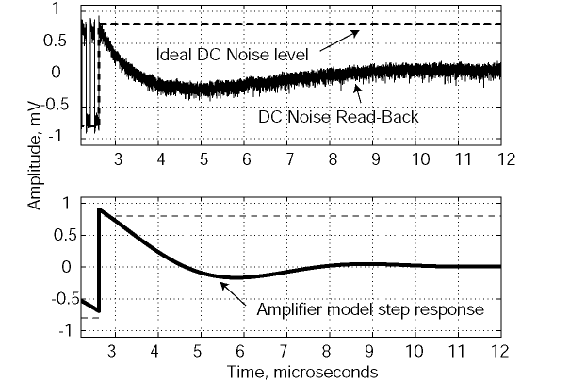
Figure 7.12 Comparison of ideal read-back for positive and negative
DC-saturated perpendicular media (top), and the step response of
the AC-coupled read-back amplifier with cut-off at 100 KHz
The exact impact of FCE and read electronics frequency response on the read-back waveform is difficult to predict. The shape distortions are to be evaluated for each particular set of recording components and operating track widths as well as linear densities.
7.3.3. Perpendicular Signal Roll-off
Since the perpendicular medium has a soft underlayer with high permeability, the magnetic “mirror” image is applied to the read sensor as well as to the write head (see Figure 7.6). Consider the read head over the perpendicular media with the SUL (Figure 7.13). The top head is “real”. The exact image of this head is created symmetrically to the upper boundary of the SUL.
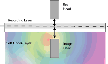
Figure 7.13 Read head and its image over perpendicular recording
media with SUL
As the read head is flying over the medium, it responds to vertical magnetic stray fields generated in the recording layer. The total read-back signal can be represented as the sum of the signals from the real GMR sensor and the imaginary sensor in the SUL. However, this “mirror” head is geometrically further away from the recording layer (the mirror image is “reflected” from the top boundary of the SUL) and suffers from spacing loss, resulting in reduced resolution. Therefore, the resolution of the system with SUL is always worse compared with the resolution of the single recording layer.
At the same time, the presence of the SUL increases the total signal – the total read-back equals the sum of the signals from the real and the “image head”.
The definition of total read-back amplitude and resolution in perpendicular recording becomes even more complicated due to the field cancellation effect (FCE): the stray field magnitude close to transition is larger compared to the field in the middle of the recorded bit. Roughly speaking, the SUL doubles the read-back voltage, however the signal level increases predominantly at low recorded densities. The read-back signal also becomes dependent on the track widths: wider data tracks demonstrate more FCE.
Therefore, the roll-off (amplitude versus recorded density) behavior of the perpendicular system is quite complicated with signal shape and amplitude depending on numerous factors, such as recording density, track width, SUL thickness, distance to the SUL etc. Intrinsically larger amplitude of the perpendicular signal at lower densities rolls off faster at higher recording density. Therefore, it is not clear how to estimate gains and losses of the perpendicular system read-back. Also, it is very difficult to compare perpendicular read-back signal with longitudinal.
As we have mentioned before, the differentiated perpendicular signal is very similar to the longitudinal. Therefore, the experimental roll-off curves for the perpendicular system and the longitudinal system with PW50, determined from the derivative of the perpendicular read-back waveform, can be compared (Figure 7.14). The signals have different signal amplitudes. The maximum amplitude is normalized to 1.
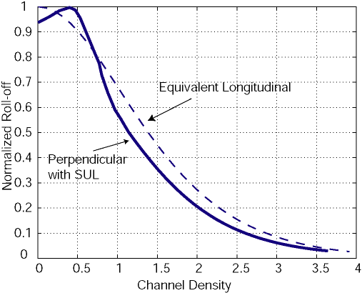
Figure 7.14 Comparison of normalized roll-off curves for perpendicular and longitudinal system with similar pulse width
This comparison of normalized roll-off curves is not completely honest – it is difficult to achieve a longitudinal PW50 as narrow, as the ones which be obtained with perpendicular recording. Assuming the same pulse width can be achieved, the perpendicular recording has intrinsically lower resolution.
Consider D10 (10%) resolution point, which is a practical limit for a detection channel. The perpendicular system roll-off is at channel density of 2.5 (channel density is defined as the pulse width to bit period ratio), while for longitudinal, the same D10 point is around channel density of 3. Therefore, for the idealized equivalent longitudinal system, the highest achievable density could be about 20% higher.
Note an interesting feature of the perpendicular roll-off curve: the lowest density signal has lower amplitudes, which become maximum at a density of around 0.5 (the absolute numbers are approximate and defined by the particular type of the perpendicular system – recording head, recording and SUL layer thicknesses, head-media separation etc). The peak of the roll-off curve is explained by the same field cancellation effect (FCE) – lower densities suffer from amplitude loss far from the transition center.
Once again, it is worth noticing, that the particular perpendicular roll-off curve strongly depends on the head and medium optimization. With all the advantages, draw-backs and limitations of the perpendicular recording system, recent experimental studies demonstrated about a 20-40% gains in the highest achievable areal density.
- A book on perpendicular recording is recently published by Kluwer Academic Press: S. Khizroev and D.Litvinov “Perpendicular Magnetic Recording”, 2004
- There are several nice review papers on the topic:
S.Khizroev and D.Litvinov “Perpendicular magnetic recording: Writing Process” – Journal of Applied Physics, vol. 95, pp.4521-4537, 2004-09-21
D.Litvinov, M.Kryder and S.Khizroev “Physics of perpendicular magnetic recording: Playback” – Journal of Applied physics, vol. 93, pp. 9155-9164, 2003
R.Wood, Y. Sonobe, Z.Jin and B. Wilson “Perpendicular recording: the promise and the problems” – Journal of Magnetism and Magnetic Materials, 235, pp. 1-9, 2001 - Comparison of longitudinal and perpendicular recording can be found in:
H. N. Bertram and M. Williams “SNR and density limit estimates: a comparison of longitudinal and perpendicular recording” –IEEE Trans. Magnetics, vol. 36, pp. 4-9, 2000 - Write head design, NLTS measurements, and background effects are described in the following papers:
S.Khizroev, M.Kryder and D. Litvinov “Next generation perpendicular systems” – IEEE Trans. Magnetics, vol.37, pp.1922-1925, 2001
M. Williams, C.Rettner, K. Takano and W. Weresin “Perpendicular write process and head design” – IEEE Trans. Magnetics, vol.38, pp. 1643-1646, 2002
W.Zhu, D. Kaiser, J. Judy and D.Palmer “Media background effect on the performance in perpendicular recording” – ,Journal of Applied Physics, vol. 93, pp.6999-7001, 2003
P.Luo, K. Stoev, F.Liu et al ” Experimental study of amplitude asymmetry effects in perpendicular recording” – IEEE Trans. Magnetics, vol. 39, pp. 2222-2224, 2003
P. van der Heiden et al. ” The effect of media background on reading and writing in perpendicular recording” – Journal of Applied Physics, vol 91, pp. 8372-8374, 2002
W. Jiang, N. Smith, M. Williams et al. “Adjacent track interference in dual-layer perpendicular recording” – IEEE Trans. Magnetics, vol. 39, pp. 1891-1896, 2003
K. Senanan and R. Victora “Theoretical study of non linear transition shift in double layer perpendicular media” – IEEE Trans. Magnetics, vol. 38, pp. 1664-1669, 2002
F. Liu, K. Stoev et al. “Perpendicular recording heads for extremely high density recording” – IEEE Trans. Magnetics, vol. 39, pp. 1942-1948, 2003
K. Stoev et al. “High Linear density study of advanced single pole head” – IEEE Trans. Magnetics, vol. 38, pp. 2243-2248, 2002 - Perpendicular PRML channels were described in:
M. Madden. M.Oberg, Z.Wu and R. He “Read channel for perpendicular magnetic recording” – IEEE Trans. Magnetics, vol. 30, pp. 241-246, 2004
R.Cidecian, E. Eleftheriou and T. Mittelholzer “Perpendicular and longitudinal recording: a signal processing and coding perpective” – IEEE Trans. Magnetics, vol. 38, pp. 1698-1704, 2002
Last Modified: January 27, 2005

